24
APPLICATION DATA
UNIT SELECTION
The horizontal units are available as cooling only and heat pumps.
For most applications, the cooling load dictates the size selection.
Select equipment to either match or be slightly less than anticipated
peak load. This provides better humidity control, fewer unit cycles,
and better low load performance.
For units used in spaces with high sensible loads, base equipment
selection on unit sensible load, not on total anticipated load to
avoid oversizing the equipment.
UNIT MOUNTING (INDOOR)
Unit leveling -- For reliable operation, units should be level in all
planes.
Clearance -- Provide adequate clearance for airflow. (See Fig. 9)
Unit location -- Select a location which will provide the best air
circulation for the room.
These units should be positioned as high as possible on the wall for
best air circulation. The unit return and discharge should not be
obstructed by furniture, curtains, or anything which may cause unit
short cycling or air recirculation. Place the unit in the middle of the
selected wall (if possible). Use an outside wall, if available, to
make piping easier, and place the unit so it faces the normal
location of room occupants.
Support -- The wall must provide adequate support for the weight
of the fan coil. Refer to the Physical Data section for fan coil
weights.
Mounting Template -- The fan coil units are furnished with
mounting templates to mark the hole locations for wiring and
refrigerant lines.
UNIT MOUNTING (OUTDOOR)
Unit leveling -- For reliable operation, units should be level in all
planes.
Clearance -- Minimum clearance, as shown in Fig. 10, must be
provided for airflow. The condensing units are designed for
free--blow application. Air inlets and outlets should not be
restricted.
Unit location -- A location which is convenient to installation and
not exposed to strong wind. If unit is exposed to strong winds it is
recommended that a wind baffle accessory be used.
A location which can bear the weight of outdoor unit and where
the outdoor unit can be mounted in a level position.
Mounting Pad -- The minimum mounting pad dimensions are
listed in the following table:
UNIT MODEL
MAXIMUM MOUNTING PAD DIMENSIONS
f t --- i n . ( m m )
38HDF018, 024, 030
38QRF018, 024
1’--- 11” X 3’---6”
(584.2 X 1066.8)
38HDF036
38QRF030, 036
2 ’ --- 0 ” X 4 ’ --- 2 ”
(609.6 X 1270)
SYSTEMS OPERATING CONDITIONS
Cooling Operating Range
Maximum Minimum
DB ° F (° C) WB ° F (° C) DB ° F (° C) WB ° F (° C)
Outdoor
Unit
125 (51.7) --- --- 55 (12.8) --- ---
Indoor
Unit
90 (32.2) 74 (23.3) 62 (17.0) 56 (13)
Heating Operating Range
Maximum Minimum
DB ° F (° C) WB ° F (° C) DB ° F (° C) WB ° F (° C)
Outdoor
Unit
75 (23.9) 67 (19.4) 17 (---8.3) --- ---
Indoor
Unit
81 (27.2) --- --- 62 (17.0) --- ---
Low Ambient Operation
Both cooling only and heat pumps will operate in cooling down to
55_F (12.8_C).
When equipped with a Low Ambient Controller, the unit will
operate down to --20_F (--28.9_C).
For proper operation of colling only units, a Winter Start Kit
(bypasses the Low Pressure Switch), a Crankcase Heater (prevents
refrigerant migration during compressor--off cycle), and a Wind
Baffle should also be installed.
On heat pumps, a Winter Start Kit will not be required. An
Isolation Relay to bypass the Low Ambient Controller when unit is
in heating mode will be required.
Metering Devices
An Accurator installed at the outdoor unit is used as a metering
device. This requires that both refrigerant lines must be insulated.
(A heat pump unit has 2 AccuRaters.)
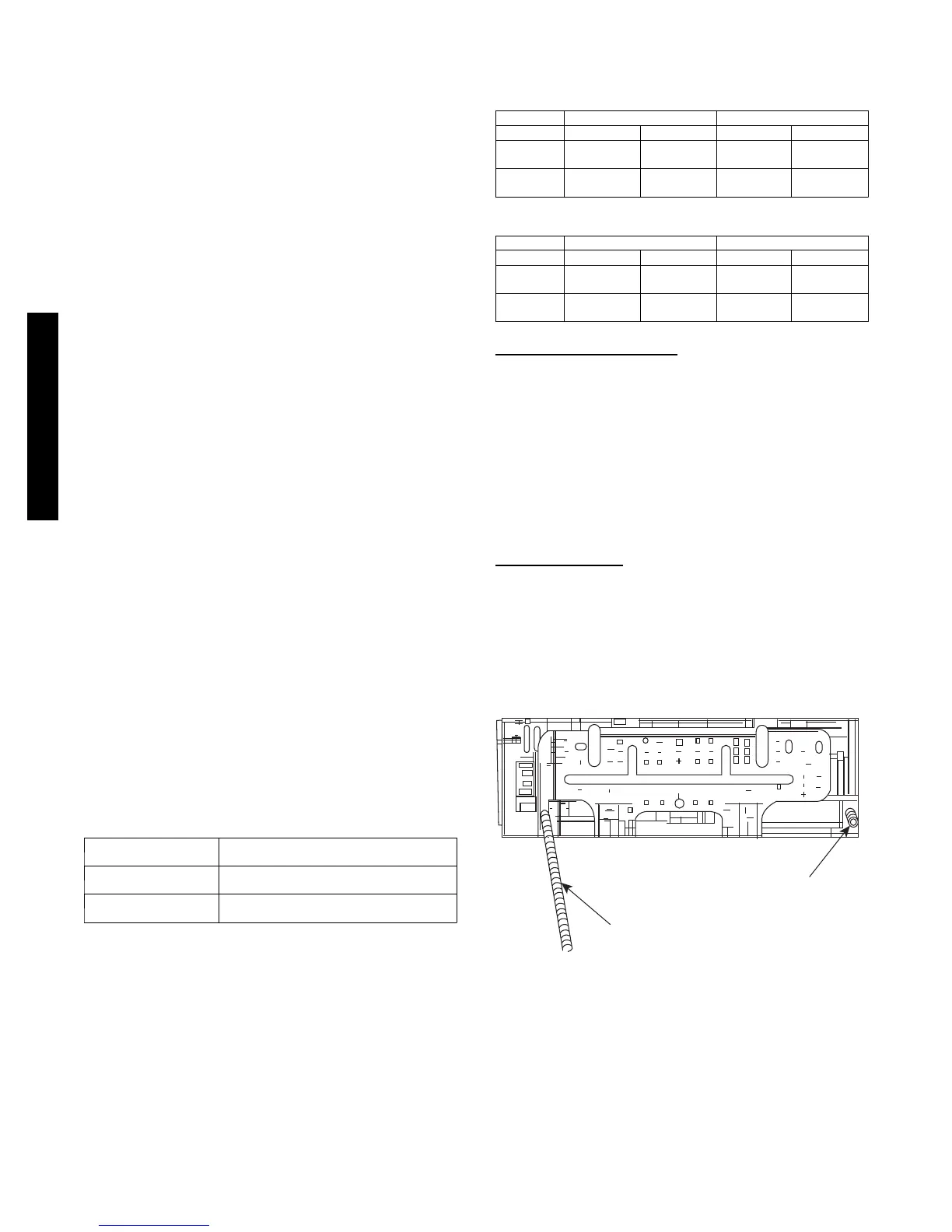
DRAIN CONNECTIONS
For ease of installation, the drains on the 40QNC/QNQ units can
be connected form either the back--left or back--right as shown in
Fig. 11.
Drain Hose
Drain Cap
A08362
Fig. 11 – Location of Drain Hose & Cap
Install drains to meet local sanitation codes. If adequate gravity
drainage cannot be provided, unit should be equipped with
accessory condensate pump. See physical dimension tables for
drain sizes.
NOTE: High wall fan coil units have internal condensate
traps. A trap is not required.
4QNC,QNQ/38HDF,QRF
 Loading...


