EasyManua.ls Logo

Carrier 42C Series - Page 60

Carrier 42C Series
100 pages
To Next Page IconTo Next Page
To Previous Page IconTo Previous Page
Loading...
60
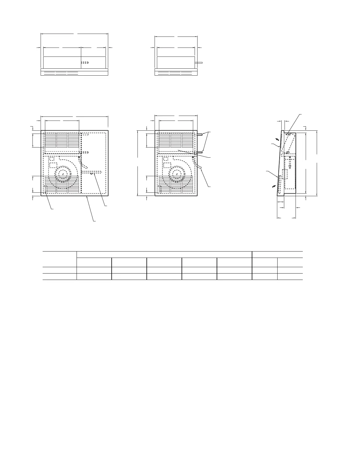
Fig. 54 — 42VGA—Vertical Recessed Cabinet
UNIT
SIZE
42VGA
DIMENSIONS – in. [mm]
a,b,c,d,e,f,g
NOTE(S):
a. Right-hand units shown, left-hand opposite.
b. All dimensions are ± .25 [6]. Drawing not to scale.
c. Product specifications are subject to change without notice.
d. Control box size and position may vary. Consult factory.
e. Position may vary.
f. Service access is located on the front of the service box.
g. Knockouts on the bottom and side of the control box for incoming connections.
QUANTITY/UNIT
ABCDEBlowerMotor
01 25-3/4 [654] 15-3/4 [400] 14 [356] 1-1 /2 [38] 12-3/4 [324] 1 1
03 39-3/4 [1010] 29-3/4 [756] 28 [711] 1-15/16 [49] 25-7/8 [657] 2 2
3/4
[19]
22
[559]
3/4
[19]
23-1/2
[597]
1
[25]
4-1/8
[105]
3
[76]
7-1/8
[181]
1
[25]
5
[127]
8
[203]
1
[25]
23-1/2
[597]
Stamped
Supply
Grille
Stamped Return
Grille
With
1" [25]
Filter
Air Vent
3/4" [19] I.D. Drain
Hose Connection
5/8" [16] O.D.
Supply and Return
Water
Connections
Removable
Front Panel
1
[25]
5
[127]
8
[203]
1
[25]
10" [254]
Valve
Compartment
Junction Box
7/8
[22]
7/8
[22]
7/8
[22]
7/8
[22]
Right Side View
Front View
Front View
Top View Top View
Return
Air
Supply
Air
(Standard Model)
(Extended Model)
Plastic
Auxiliary
Drain Pan
(Ship Loose)
A
C
10
C
B
E
D
E
D
A
B

Table of Contents

Other manuals for Carrier 42C Series

Related product manuals