66
42V UNITS
Vertical Series Unit Installation (42VAD)
Vertical unit models are designed to be floor mounted or otherwise
supported from below and bolted to the wall or floor structure
through the mounting holes provided in the chassis. These units
may be wall hung only when originally ordered from the factory
for wall-mount applications.
The type of mounting device is a matter of choice; however, the
mounting point shall always be that provided in the chassis or cab
-
inet. Fasteners and other required hardware must be field-
supplied. Refer to the unit product drawings for hole mounting
locations and sizes.
FLOOR/WALL MOUNT INSTALLATION
Floor Mount Units
1. Select the unit location. Allow for adequate space for free air
circulation, service clearances, piping and electrical connec-
tions, and any necessary ductwork.
2. Make sure the floor is able to support the weight of the unit.
See submittal drawings for nominal unit weight.
3. Ensure wall behind unit is smooth and plumb; if necessary,
install furring strips on walls with irregular surfaces or mul-
lions. Furring strips must be positioned behind mounting
holes in unit. Fasteners, furring strips, and other seals (if
required) must be field-supplied.
4. Remove all wall and floor moldings from behind the unit.
5. Adjust optional unit leveling legs so unit is level. Unit must
be level for proper operation and condensate drainage.
CABINET FRONT PANEL INSTALLATION AND
REMOVAL
For 42VBD/VFD cabinet units, replace the front panel by aligning
the bottom tabs on the unit with the respective slots on the panel
bottom. Align the top edge of the unit with the panel. Refer to
Table
5 for hole locations and see Fig. 66 and 67 for unit mounting
dimensions.
Wall Mount Units
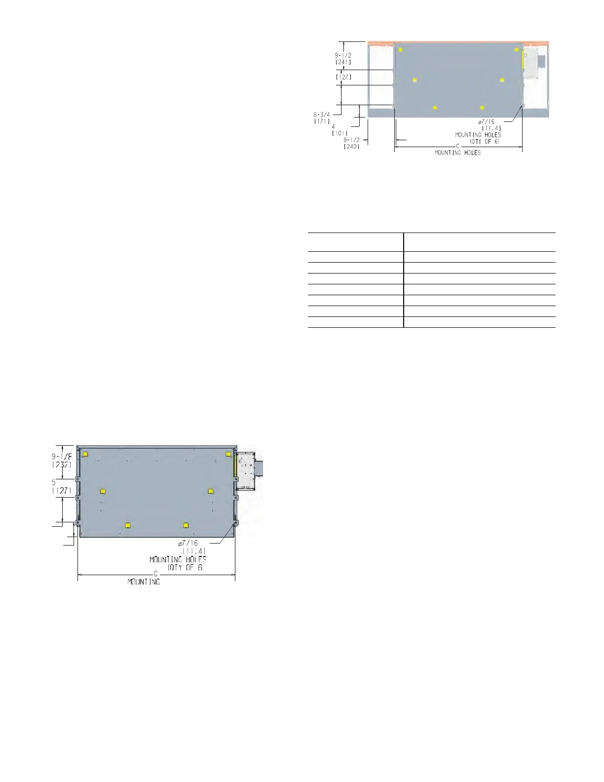
Fig. 66 — Wall Mount Hanger Hole Locations –
42VAD
Fig. 67 — Wall Mount Hanger Hole Locations –
42VBD/VFD
1. Prepare wall openings for recessed units. Reference submittal
drawings for unit size dimensions.
2. Mark the position of the hanger holes on the wall according
to the dimensions. See Fig. 66 or 67 and Table 5. Align the
hole locations evenly.
3. Prepare the field-provided installation hardware before set-
ting the unit in place.
4. For Cabinet Units, remove the front panel before installation.
5. Mount the unit on the hanger hardware. Test to verify the unit
is properly supported.
6. Complete piping and wiring connections, in addition to any
necessary ductwork to the unit as instructed in the following
sections. Ensure that the auxiliary drain pan is in position for
coil drain, when applicable.
7. Reinstall the front panel (cabinet units) before start-up.
NOTE: Dimensions are in inches [mm].
Table 5 — C Dimension for Wall Mount Hanger Hole
Locations
UNIT MODEL
C DIMENSION – MOUNTING HOLES
in. [mm]
02 23 [584]
03 27 [686]
04 33 [838]
03 43 [1092]
08 45 [1143]
10 59 [1499]
12 67 [1702]
NOTE: Dimensions are in inches [mm].

 Loading...


