71
NOTE: The project specifications for system pressure, pressure
drop limitations, and flow rate should be checked prior to selection
of specific components or the valve package size.
STEAM CONNECTIONS
On units with steam heating coils, the maximum steam pressure
applied to the unit should never exceed 10 psig. However, when
steam is used on a 4-pipe application system with 1-row and
2-row coils the maximum steam pressure should never exceed 5
psig (suitable for only low-pressure steam).
Do not drain the steam mains or take-off through the coils. Drain
the mains ahead of the coils through a steam trap to the return line.
Overhead returns require 1 psig of pressure at the steam trap dis
-
charge for each 2 ft of elevation to ensure continuous condensate
removal.
Proper steam trap selection and installation is necessary. As a
guideline in creating a steam trap, locate the steam trap discharge
at least 12 in. below the condensate return connection. This pro
-
vides sufficient hydrostatic head pressure to overcome trap losses
and ensure complete condensate removal.
DIRECT EXPANSION (DX) REFRIGERANT PIPING
Use the condensing unit manufacturer's recommended line sizes
and requirements. Suction line must be insulated for correct opera-
tion. Use refrigerant-grade copper lines only. The unit is not ap-
plied as a heat pump.
Thermostatic expansion valve (TXV) and sensing bulb are
factory-installed on units when DX coil option is chosen with dis
-
tributor and TXV. The TXV is equipped with an external equalizer
connection to allow pressures to equalize when the compressor is
shut off. The equalizer piping connection must be made in the
field.
NOTE: If a hot water coil is used in the reheat position, a field-
supplied freezestat must be installed to protect the coil.
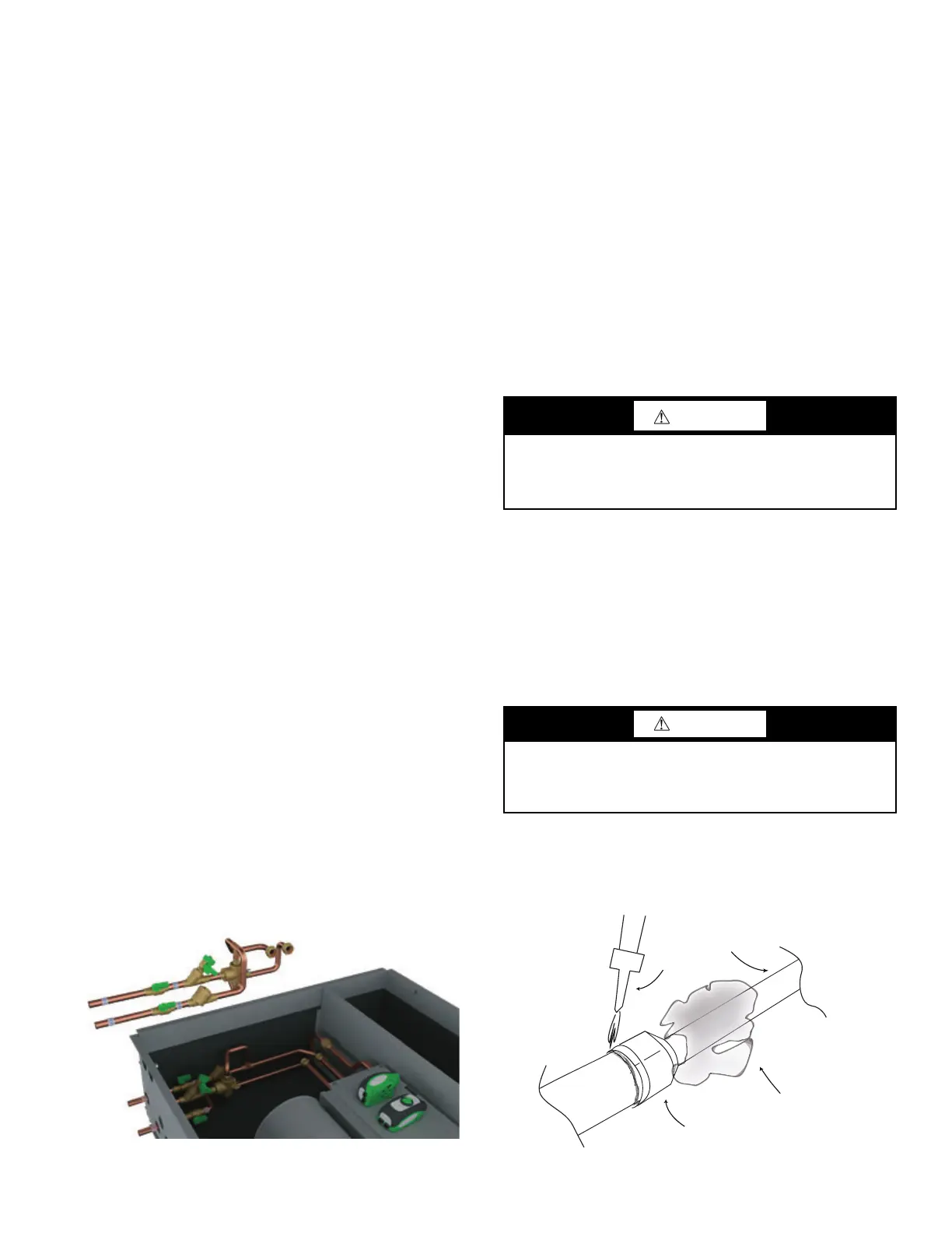
General Assembly
1. For 42CG and 42CK units, factory provides tube extensions
to penetrate the rear of the fan coil cabinet. Chilled and hot
extension tubes must be properly insulated. See Fig. 79.
2. Remove valve actuators temporarily during valve installation.
Protect unit wiring from damage.
3. Install valve packages and connect to the coil in sequence,
first heating, then cooling.
4. Torque unions tight using backup wrench to prevent damage
to coil tubes. Align exiting tubes to the center of the pipe
openings.
5. If desired, apply split bushings or grommets (provided by
others) to the pipes for mechanical support and protection. Do
not allow copper tube to contact steel cabinet.
6. Now is a good time to leak test the unions and fittings, using
air pressure and soap. The coil air vent(s) may be used for this
purpose.
Fig. 79 — General Valve Package Assembly
(CG Unit Shown)
If none of the above factory accessories have been provided with
the units, a drip lip (available from the factory) may still be
required to direct piping condensate into the unit drain pan.
After the connections are completed, the system should then be
tested for leaks. Since some components are not designed to hold
pressure with a gas, hydronic systems should be tested with water.
Pressure testing should be completed prior to sheet rocking or
painting.
Refrigerant systems should be tested with dry nitrogen rather than
air to prevent the introduction of moisture into the system. In the
event that leaking or defective components are discovered, the
Sales Representative must be notified BEFORE any repairs are
attempted. All leaks should be repaired before proceeding with the
installation.
After system integrity has been established, insulate the piping in
accordance with the project specifications. This is the responsibili
-
ty of the installing or insulation contractor. All chilled water piping
and valves or refrigerant suction piping not located over drain
pans or drip lips must be insulated to prevent damage from sweat
-
ing. This includes factory and field piping inside the unit cabinet.
TEST AND INSULATE
When all joints are complete, perform hydrostatic test for leaks.
Vent all coils at this time. Check interior unit piping for signs of
leakage from shipping damage or mishandling. If leaks are found,
notify your Carrier representative before initiating any repairs. Re
-
lease trapped air from system.
Never pressurize any equipment beyond specific test pressure. Al-
ways pressure-test with an inert fluid or gas, such as clear water or
dry nitrogen, to avoid possible damage or injury in the event of a
leak or component failure during testing.
Following the hydrostatic test, insulate all piping to prevent
sweating.
To ensure compliance with building codes, restore the structure's
original fire resistance rating by sealing all holes with material car
-
rying the same fire rating as the structure. See Fig. 80 and Table 7.
Fig. 80 — Field Piping Connections
CAUTION
All water coils must be protected from freezing after initial
filling with water. Even if the system is drained, unit coils may
still hold enough water to cause damage when exposed to tem-
peratures below freezing.
CAUTION
All water coils must be protected from freezing after initial
filling with water. Even if system is drained, unit coils may
still have enough water to cause damage when exposed to tem-
peratures below freezing.
Field
Tubing
Wet Rag
Torch
Supply
or
Return
Adaptor
(Factory Installed)
Stub
From Coil

 Loading...


