77
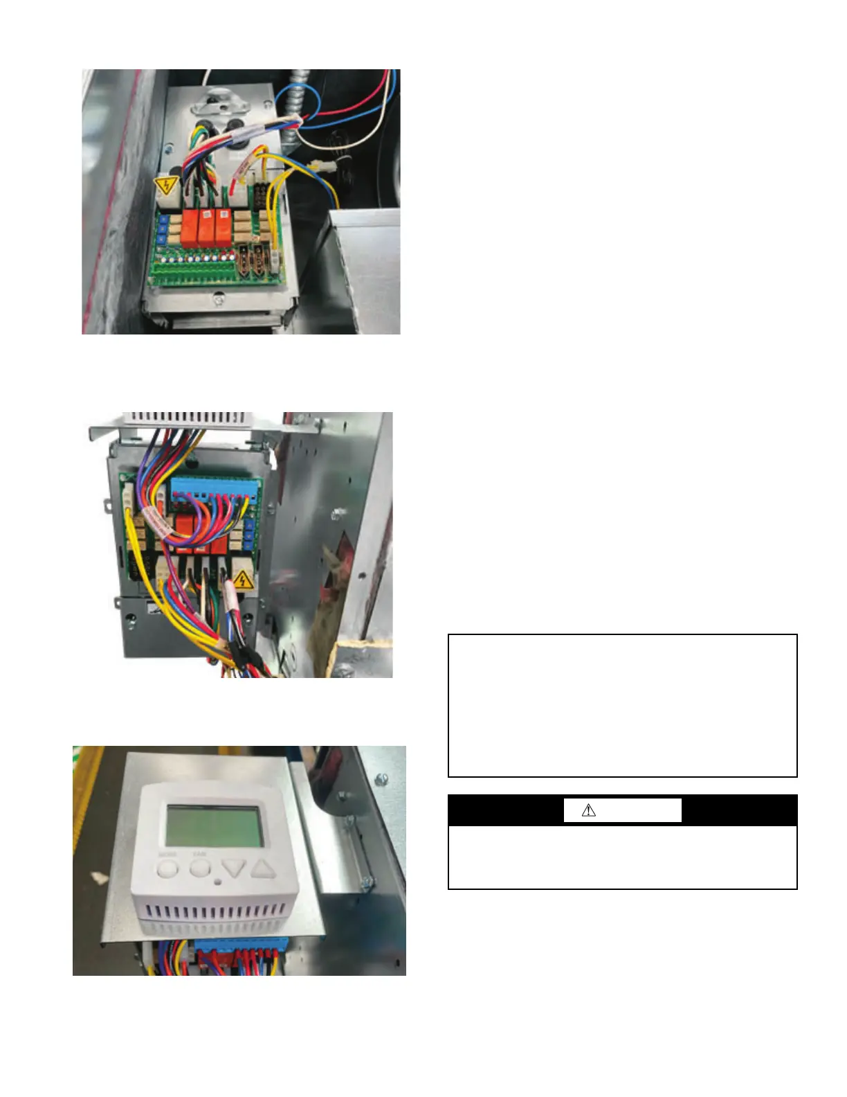
Fig. 83 — Unit-mounted Control Box Access
Fig. 84 — External Unit-mount Control Box Access
Fig. 85 — Thermostat Unit-Mount
Step 5 — Make Ductwork Connections
All ductwork and/or supply and return grilles should be installed
in accordance with the project plans and specifications. If not in
-
cluded on the unit or furnished from the factory, supply and return
grilles should be provided as recommended in the product catalog.
For units with no return-air ductwork, check local code require
-
ments for possible application restrictions. All units must be in-
stalled in areas that are non-combustible.
Some models are designed to be connected to ductwork with a
MINIMUM amount of external static pressure. These units may
be damaged by operation without the proper ductwork connected.
Consult the approved submittals and the product catalog for unit
external static pressure limitations.
Units provided with outside air for ventilation should have some
form of low-temperature protection to prevent coil freeze-up. This
protection may be any of several methods such as a low-tempera
-
ture thermostat to close the outside air damper or a preheat coil to
temper the outside air before it reaches the unit.
It should be noted that none of these methods will adequately pro-
tect a coil in the event of power failure. The safest method of
freeze protection is to use glycol in the proper percent solution for
the coldest expected air temperature.
HORIZONTAL PLENUM TYPE
42CE units may be shipped with a bottom return-air inlet. These
units may be converted to rear return by removing the bottom
inlet filter retainer clips and filter, then removing the plenum rear
panel. The rear panel must then be moved to the bottom of the
unit and reversed so that the top edge (when rear mounted) is
toward the supply end of the unit and reinstalled on the bottom
of the plenum. The panel should be positioned towards the drain
pan to expose the one-inch wide filter slot for unit-mounted filters.
The panel should be positioned against the rear bottom brace
completely covering the bottom of the plenum on units with
remote filters.
HI-PERFORMANCE PLENUM TYPE
42DC units may be shipped with a bottom return- air inlet. These
units may be converted to rear return by simply exchanging the
bottom and rear plenum panels.
NOTE: Image depicts control box mounted in 42CK unit.
NOTE: Image depicts control box mounted on 42VCA unit.
NOTE: Image depicts control box with thermostat mounted on
42VCA unit.
IMPORTANT: Flexible duct connections should be used on all
air handling equipment to minimize vibration transmissions. All
ductwork and insulation should be installed to allow proper
access to all components for service and repair such as filters,
motor/blower assemblies, etc.
The manufacturer assumes no responsibility for undesirable sys-
tem operation due to improper design, equipment or component
selection, and/or installation of base unit, ductwork, grilles, and
other related components.
CAUTION
Prevent dust and debris from settling in unit. If wall finish or
color is to be spray-applied, cover all openings to prevent
spray from entering unit. Failure to do so could result in dam-
age to the unit and/or the reduction of unit efficiency.

 Loading...


