76
Step 4 — Make Electrical Connections
The electrical service to the unit should be compared to the unit
nameplate to verify compatibility. The routing and sizing of all
piping, and the type and sizing of all wiring and other electrical
components such as circuit breakers, disconnect switches, etc.
should be determined by the individual job requirements. Verify
the electrical conductor size is suitable for the distance to the
equipment connection and will support the equipment electrical
load. All installations should be made in compliance with all gov
-
erning codes and ordinances. Compliance with all codes is the
responsibility of the installing contractor.
The unit serial plate lists the unit electrical characteristics such as
the required supply voltage, fan and heater amperage and required
circuit ampacities. The unit wiring diagram shows all unit and
field wiring. Since each project is different and each unit on a proj
-
ect may be different, the installer must be familiar with the wiring
diagram and serial plate on the unit BEFORE beginning any
wiring.
All components furnished for field installation by either the facto-
ry or the controls contractor should be located and checked for
proper function and compatibility. All internal components should
be checked for shipping damage, and any loose connections
should be tightened to minimize problems during start-up.
Any devices such as fan switches or thermostats that have been
furnished from the factory for field installation must be wired in
strict accordance with the wiring diagram that appears on the unit.
Failure to do so could result in personal injury or damage to com
-
ponents and will void all manufacturer’s warranties.
The fan motor(s) should never be controlled by any wiring or
device other than the 3-speed switch or thermostat/ switch combi
-
nation without factory authorization. Fan motor(s) may be tempo-
rarily wired for use during construction only with prior factory
approval in strict accordance with the instructions issued at that
time.
Units with optional factory-furnished and installed aquastats may
be shipped with the aquastats mounted on a coil stub-out. Remove
the aquastat before installation of a valve package. Consult the
factory piping diagram in the approved submittals for proper loca
-
tion when reinstalling the aquastats. If the valve package is field-
furnished, the aquastat must be installed in a location where it will
sense the water temperature regardless of control valve position. A
bleed bypass may be required to guarantee proper aquastat
operation.
All field wiring should be done in accordance with governing
codes and ordinances. Any modification of the unit wiring without
factory authorization will void all of the factory warranties, and
will nullify any agency listings.
The manufacturer assumes no responsibility for any damages and/
or injuries resulting from improper field installation and/or wiring.
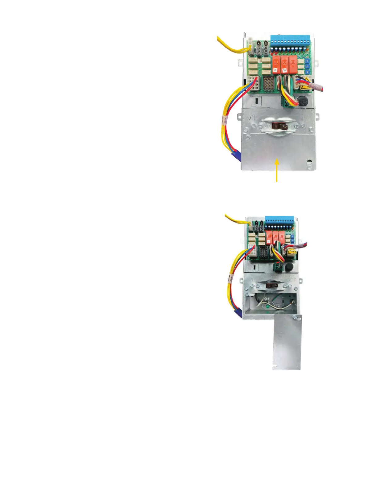
1. After planning for and bringing incoming power to the unit,
locate the control box and cover plate (incoming electrical
power wiring compartment). Refer to Fig. 81.
2. Determine appropriate knock out to feed incoming power
wiring into box.
3. Loosen screws to rotate cover plate to access wiring. Refer to
Fig. 82.
4. Secure incoming power wiring with proper service entrance
connector and/or appropriate strain relief. Use wire nuts
connections that meet wire gauge requirements. See
Fig. 83-85.
5. Replace cover plate and secure screws.
Fig. 81 — Control Box with Cover Plate
Fig. 82 — Loosened Covered Plate
Incoming Electrical Power
Wiring Compartment

 Loading...


