81
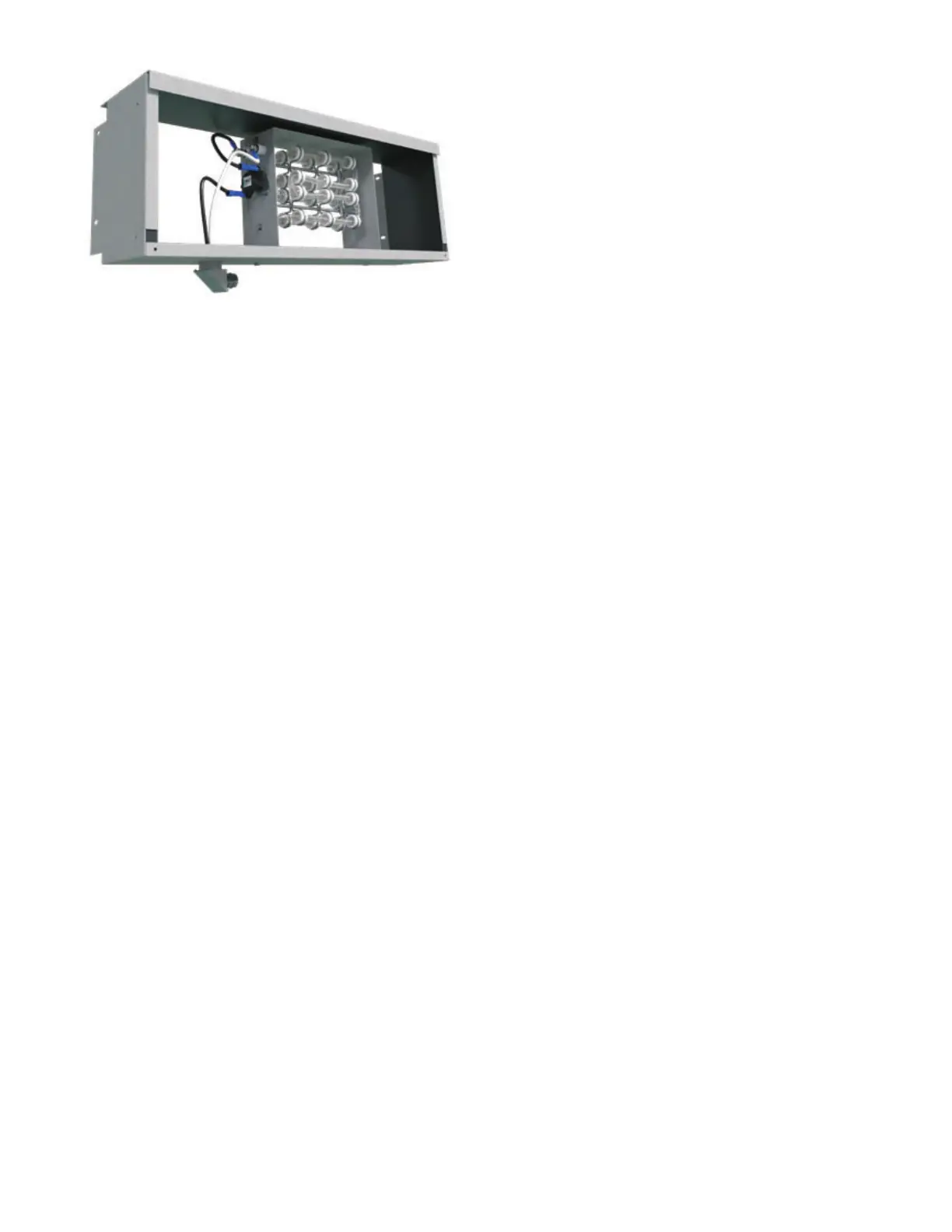
Fig. 88 — Exposed Wire Heater
Electrical Wiring and Controls
The electrical operation of each unit is determined by the compo-
nents and wiring of the unit. This may vary from unit to unit. Con-
sult the wiring diagram attached to the unit for the actual type and
number of controls provided on each unit. See Appendix A and
Fig.
I for wiring diagram.
The integrity of all electrical connections should be verified at
least twice during the first year of operation. Afterwards, all con-
trols should be inspected regularly for proper operation. Some
components may experience erratic operation or failure due to
age. Wall thermostats may also become clogged with dust and lint,
and should be periodically inspected and cleaned to provide reli
-
able operation.
When replacing any components such as fuses, contactors, or
relays, use only the exact type, size and voltage component as fur
-
nished from the factory. Any deviation without factory authoriza-
tion could result in personnel injury or damage to the unit. This
will also void all factory warranties. All repair work should be
done in such a manner as to maintain the equipment in compliance
with governing codes, ordinances and testing agency listings.
Filters, Throwaway
The type of throwaway filter most commonly used on fan coil
units should be replaced on a regular basis. The time interval be
-
tween each replacement should be established based on regular in-
spection of the filter, and should be recorded in the log for each
unit. Refer to the product catalog for the recommended filter size
for each product type and size. If the replacement filters are not
purchased from the factory, the filters used should be the same
type and size as those furnished from, or recommended by the fac
-
tory. Pleated media, or extended surface filters should not be used
since the high air pressure drops encountered with these types of
filters is not compatible with the type of fan coil unit covered in
this manual. Consult the factory for applications using filter types
other than the factory standard or optional product.
Filters, Permanent
A maintenance schedule for permanent filters should be devel-
oped in the same manner as throwaway filters. Unlike throwaway
filters, permanent filters may be cleaned and re-installed in the
unit instead of being discarded when dirty. The optional factory
permanent filter may be cleaned in hot soapy water to remove any
trapped dirt. It should then be set aside on edge to dry.
Before replacing the filter in the unit, it should be recharged with
some type of entrapment film such as "Film-Cor Recharging Oil."
The filter should be sprayed on both sides or submerged in the
film to assure complete coverage. The filter should not be allowed
to soak in the film, but should be immediately removed and the
excess film drained from the filter before re-installation in the unit.
Consult a local filter supplier for types of available cleaning solu
-
tions and charging films.
It should be noted that permanent filters normally have less static
pressure loss than throwaway filters.
Replacement Parts
Factory replacement parts should be used wherever possible to
maintain unit performance, it's normal operating characteristics,
and the testing agency listings. Replacement parts may be pur
-
chased through a local Sales Representative.
Contact the local Sales Representative or the factory before at-
tempting any unit modifications. Any modifications not autho-
rized by the factory could result in personnel injury, damage to the
unit, and could void all factory warranties.
When ordering parts, the following information must be
supplied to ensure proper part identification:
• Complete unit model number
• Unit serial number
• Complete part description, including any numbers
For warranty parts inquiries, in addition to the information previ-
ously listed, a description of the issue with the parts is required.
Contact the factory for authorization to return any parts, such as
defective parts, to be replaced in warranty. All shipments returned
to the factory must be marked with a Return Authorization
Number which is provided by the factory, if warranty has been
approved.
On warranty replacements, in addition to the information previ-
ously listed, the unit shipping code which appears on the upper
right-hand corner of the serial plate is required. Contact the factory
for authorization to return any parts such as defective parts re
-
placed in warranty. All shipments returned to the factory must be
marked with a Return Authorization Number which is provided
by the factory.
Valves and Piping
No formal maintenance is required on the valve-package compo-
nents most commonly used with fan coil units other than a visual
inspection for possible leaks in the course of other normal periodic
maintenance. In the event that a valve should need replacement,
the same precautions taken during the initial installation to protect
the valve package from excessive heat should also be used during
replacement.
NOTES:
1. For 42CA, CE, CK, and CG size and number of elements varies
with models.
2. For 42DD units heater is located below the coil.

 Loading...


