72
LEGEND
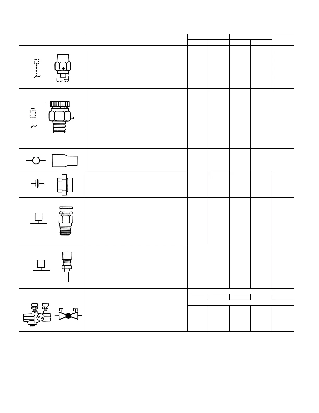
Table 7 — Piping Components
SYMBOL/SKETCH DESCRIPTION
C
V
FACTOR RATING
a
STEAM
USE
1/2 3/4 psi F
MANUAL AIR VENT: Threaded brass needle valve
with screwdriver slot for adjustment.
Application — Body brazed into high point of heating
and cooling coils for bleeding air from coil. Standard
item on all hydronic coils. Should not be used in lieu of
main system air vents.
N/A N/A 400 100 NO
AUTOMATIC AIR VENT: Nickel plated brass valve,
fiber-disc type, with positive shut-off ballcheck and
quick vent feature via knurled vent screw.
Application — Optional replacement for manual air
vent. Automatically passes minute quantities of air
through the fiber discs which expand upon contact
with water, completely sealing the valve. As air
accumulates, the fiber discs dry and shrink, repeating
the cycle. Not recommended for removing large quan-
tities of air encountered during initial start-up or
subsequent draining and refilling. Should not be used
in lieu of main system air vents. NOTE: Not recom-
mended for use in systems with glycol.
N/A N/A 125 240 NO
SWAGE: Copper tube end expanded to accept a cop-
per tube of the same size for factory or field brazing.
Application — Used where possible for all tubing joints
for best joint integrity.
N/A N/A 300 200 YES
UNION: Combination wrought copper/cast brass
union assembly, solder by solder.
Application — Used for quick connect (and discon-
nect) of valve package components to minimize field
labor and facilitate servicing of unit.
N/A N/A 300 200 YES
INSERTION TEST PORT: Brass body valve
for acceptance of test probe (up to 1/8 in.
diameter).
Application — Installed on one (or both) sides of the
coil to allow for temperature or pressure sensing. Used
for close tolerance water balancing and service
analysis.
N/A N/A 250 250 NO
PRESSURE TEST PORT: Brass body 1/4 service
access fitting with removable depressor type core.
Application — Installed on both sides of the coil to
allow for pressure sensing. Attach pressure gages to
facilitate close tolerance water balancing.
N/A N/A 400 210 NO
CIRCUIT SETTER: Variable water flow balancing
valve with manual adjustment knob, pointer, percent-
open scale, memory stop and integral pressure read-
out ports.
Application — Used for close tolerance water flow bal-
ancing. Positive shut-off ball valve feature allows
usage as combination balancing and shut-off valve.
With Pressure Ports Only
2.12 3.9 300 250 NO
With Pressure And Temperature Ports
1.6 3.4 200 250 NO
a. Check all system component pressure ratings (coils, values, pumps, etc.) with manufacturer and any applicable local or national piping codes prior to specifying system
pressure rating.
Cv — Coefficient of Velocity
ETO — Engineered to Order

 Loading...


