73
LEGEND
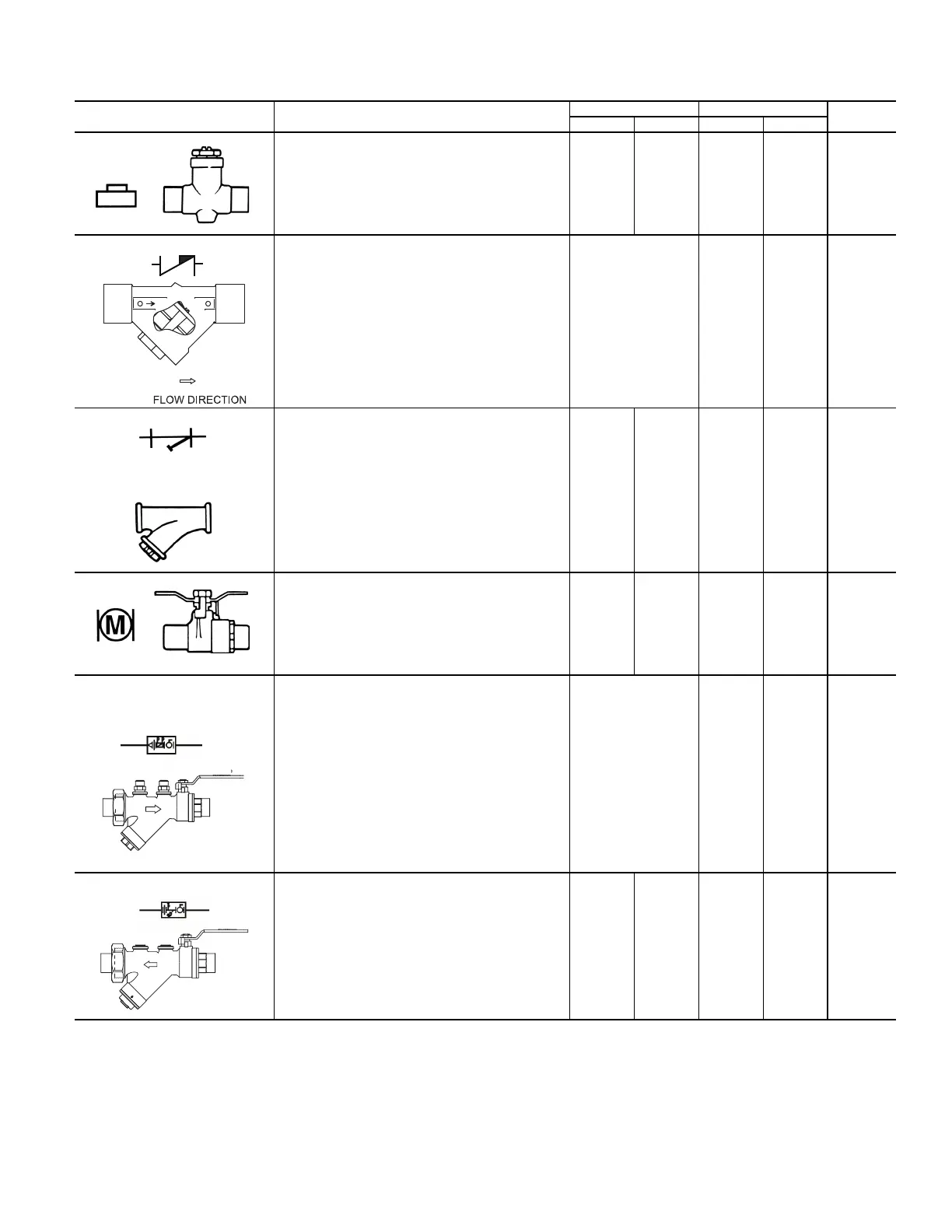
Table 7 — Piping Components (cont)
SYMBOL/SKETCH DESCRIPTION
C
V
FACTOR RATING
a
STEAM
USE
1/2 3/4 psi F
BALANCE VALVE: Variable water flow manual balancing
valve with screwdriver slot adjustment screw.
Application — May be used in 3-way valve bypass line to
permit equal flow balancing.
3 8.9 150 200 NO
FIXED FLOW VALVE: Flexible orifice type (non-adjustable).
Application — Used for water flow balancing. Valve
automatically adjusts the flow to within 10% of set point.
Operating Range: 2-80 psid
Valve orifice size
determines C
V
factor.
The orifice of these fixed
flow valves changes as
flow is regulated. As the
water pressure
increases, the orifice size
decreases, thereby
automatically limiting the
flow rate to the specified
gpm (±10%).
600 220 NO
STRAINER: Y-type body (optional with blowdown) with 20
mesh stainless steel screen.
Application — Used for removal of small particles from
system water during normal system operation. Should not
be used in lieu of main system strainers. Strainer screen
may have to be removed during initial high pressure system
flushing during start-up. Screen should be removed and
cleaned per normal maintenance schedule (provisions for
strainer blow-down not provided).
5.5
Clean
9.0
Clean
600 325 N/A
BALL VALVE WITH MEMORY STOP: Manual balance and
shut-off valve.
Application — Used for unit isolation and water flow
balancing. The adjustable memory stop feature allows return
to the balance point after shut-off. Check specifications for
service fittings required when used for water balancing.
Full Port Full Port 600 325 N/A
RETURN COMBO VALVE: A combination automatic flow
control valve, ball valve, and union end. Valve comes
standard with two pressure and temperature test plugs.
Application — Instead of adding individual components,
utilize the combination valve to save cost. Fixed flow used
for water flow balancing.
Valve orifice size
determines C
v
factor. The
orifices of these fixed
flow valves changes as
flow is regulated. As the
water pressure
increases, the orifice size
decreases, thereby
automatically limiting the
flow rate to the specified
GPM (± 10%).
600 220 N/A
SUPPLY COMBO VALVE: Includes union, ball valve,
y-strainer with blowdown, and P-T port.
Application — Instead of adding individual components,
utilize the combination supply valve to save cost. Y-strainer
with blowdown used for removal of small particles from
system water during normal system operation. Should not
be used in lieu of main system strainers. Strainer screen
may have to be removed during the initial high pressure
system flushing during start-up. Screen should be removed
and cleaned per normal maintenance schedule.
5.5 Clean 9.0 Clean 600 325 N/A
a. Check all system component pressure ratings (coils, values, pumps, etc.) with manufacturer and any applicable local or national piping codes prior to specifying system
pressure rating.
Cv — Coefficient of Velocity
ETO — Engineered to Order

 Loading...


