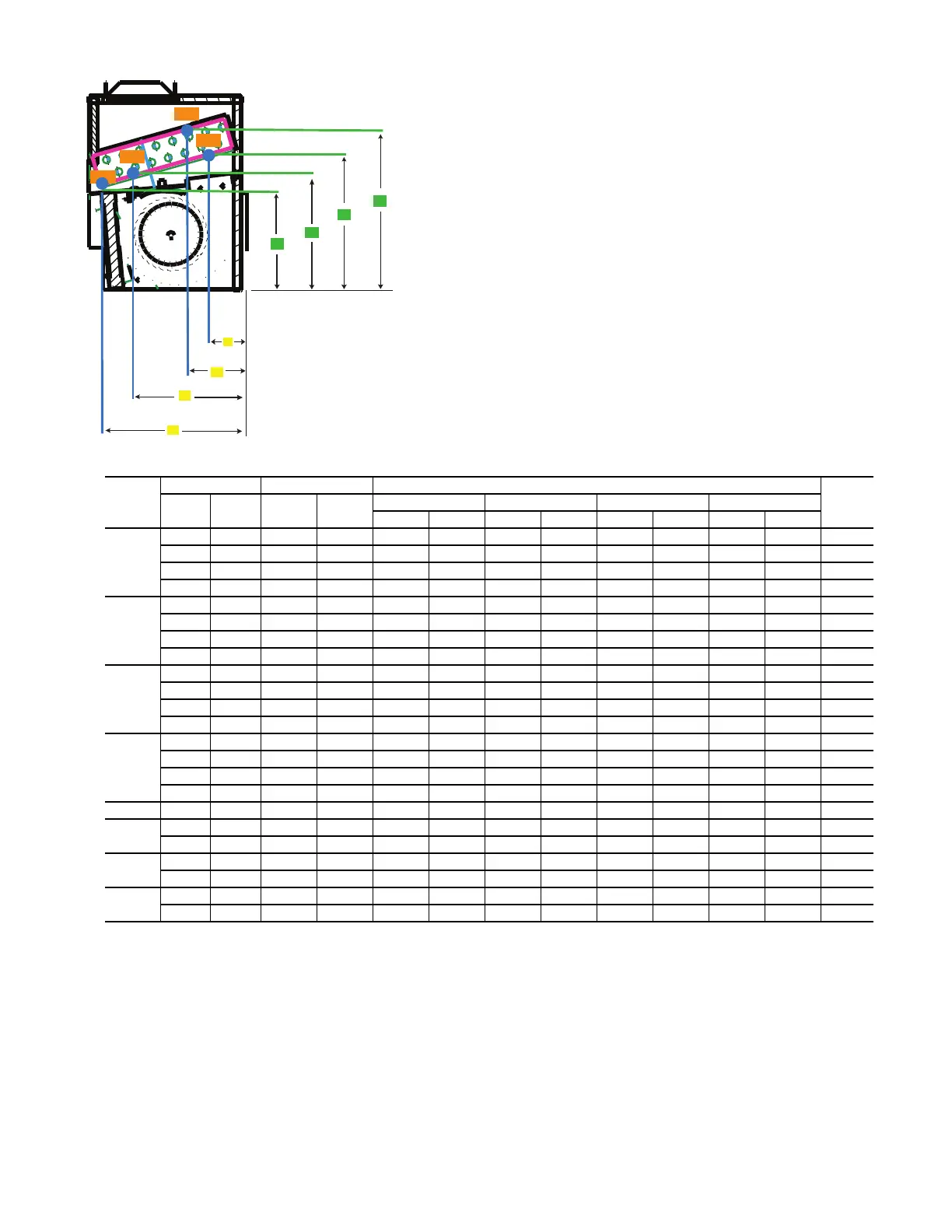
Fig. 56 — 42V*A Piping Connection Location - Hydronic Cooling and Heating Coils
a. Piping connection dimensions are consistent for either right hand or left hand connections.
b. Horizontal dimensions measured from rear panel. Vertical dimensions measured from bottom panel.
c. Measurements do not apply to same side piping and controls.
d. OE designates opposite end connection.
UNIT
SIZE
COIL ROWS CIRCUITS VCA, VEA (1-3 ROWS)
NOTES
COOL HEAT COOL HEAT
CS CR HS HR
ABCDEFGH
VEA02
2—1 —9-1/29-6/710-2/31-3/4—————
3—1 —10-3/59-4/510-8/94/5—————
2 1 1 1 9-2/5 10-1/8 10-8/9 4/5 10-3/5 9-4/5 13 1-2/5
2 1 1 1 9-2/5 10-1/8 10-8/9 4/5 10-8/9 4/5 13 1-2/5 OE
VEA03
2—1 —9-1/29-7/910-2/31-2/3—————
3—1 —10-3/59-4/510-8/94/5—————
2 1 1 1 9-2/5 10-1/8 10-8/9 4/5 10-3/5 9-4/5 13 1-2/5
2 1 1 1 9-2/5 10-1/8 10-8/9 4/5 10-8/9 4/5 13 1-2/5 OE
VEA04
2—1 —9-1/29-7/910-2/31-2/3—————
3—2 —101011-1/31-1/4—————
2 1 1 1 9-2/5 10-1/8 10-8/9 4/5 10-3/5 9-4/5 13 1-2/5
2 1 1 1 9-2/5 10-1/8 10-8/9 4/5 10-8/9 4/5 13 1-2/5 OE
VEA06
2—2 —8-8/99-8/911-2/71-1/2—————
3—2 —101011-1/31-1/4—————
2 1 2 1 9 9-2/3 11-1/3 1-1/4 10-3/5 9-4/5 13 1-2/5
2 1 2 1 9 9-2/3 11-1/3 1-1/4 10-8/9 4/5 13 1-2/5 OE
VCA02 3 1 1 1 11 10-2/7 10-1/2 1-2/7 12-1/7 9-8/9 13 -5/6 1-2/7 —
VCA03
3 1 1 1 11 10-2/7 10-1/2 1-2/7 12-1/7 9-8/9 13- 5/6 1-2/7 —
2 2 1 1 8-5/6 9-8/9 11-5/7 8/9 11 10-2/7 13 -5/6 1-2/7 —
VCA04
3 1 2 1 10-1/2 9-8/9 11 1 12-1/7 9-8/9 13 -5/6 1-2/7 —
2 2 1 1 10 9-1/2 10-1/2 1-2/7 12-1/7 9-8/9 12- 5/8 1-5/7 —
VCA06
3 1 2 1 10-1/2 9-8/9 11 1 12-1/7 9-8/9 13 -5/6 1-2/7 —
2 2 2 2 9-3/7 9-2/3 11 1 11-5/9 10 13 -2/9 1-1/2 —

 Loading...


