94
APPENDIX D — PIPING AND VALVE CONNECTIONS (CONT)
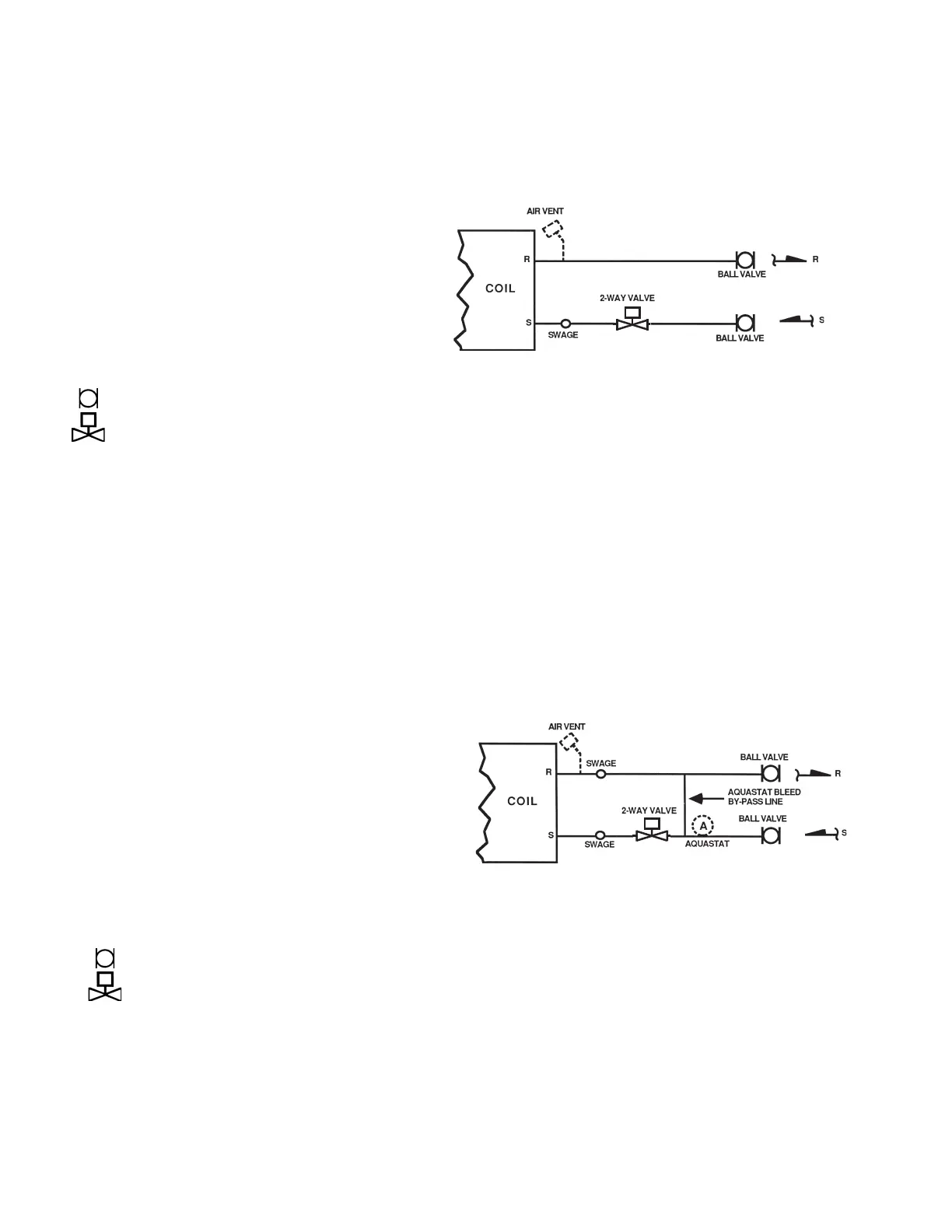
Fig. N — Two-Way Motorized Control Valve Package
Fig. O — Two-Way Motorized Control Valve Package With Aquastat Bleed Bypass Line
The 2-way motorized valve motor drives valve open and a
spring returns valve to normally closed position (no water
flow with unit OFF).
Supply connection at coil will be swage fit for field braze
(standard) or union (option). Return connection at coil will
be factory brazed if isolation valve only. Addition of any
other component will require swage fit for field braze or
optional union connection.
Check job specifications for system pressure, pressure
drop limitations and flow rate prior to selecting valve pack-
age components or valve package size (1/2 in., 3/4 in.,
etc.).
2-PIPE SYSTEM (One Valve Package) or 4-PIPE SYSTEM
(Two Valve Packages) Application:
• 2-Pipe — Hydronic Heating Only
• 2-Pipe — Hydronic Cooling Only
• 2-Pipe — Hydronic Cooling with Total Electric Heat
• 4-Pipe — Hydronic Cooling and Heating
LEGEND
NOTE: A 1/4 in. bypass line is included in the piping package when
a 2-way valve is specified with a control package containing an
automatic changeover device.
Ball Valve
Motorized 2-Way Valve
M
MOTORIZED
The 2-way motorized valve motor drives valve open and a
spring returns valve to normally closed position (no water
flow through coil with unit OFF).
The aquastat bleed bypass bleeds a small amount of water
from supply to return when control valve is closed (required
for system water temperature sensing by aquastat).
Aquastat (A) clips on supply line upstream from aquastat
bleed bypass (as shown at right). It senses system water
temperature to prevent cooling operation with hot water in
system piping or heating operation with chilled water in
system piping. Additional aquastat is required to lock out
the optional auxiliary electric heat when hot water is in the
system.
Supply and return connections at coil will be swage fit for
field braze (standard) or unions (option).
Check job specifications for system pressure, pressure
drop limitations and flow rate prior to selecting valve pack-
age components or valve package size (1/2 in., 3/4 in.,
etc.).
2-PIPE SYSTEM (One Valve Package) Application:
• 2-Pipe — Hydronic Cooling and Heating
• 2-Pipe — Hydronic Cooling and Heating with Auxiliary
LEGEND
NOTE: Additional aquastat required as noted above.
Ball Valve
Motorized 2-Way Valve

 Loading...


