50
12
11
10
9
13
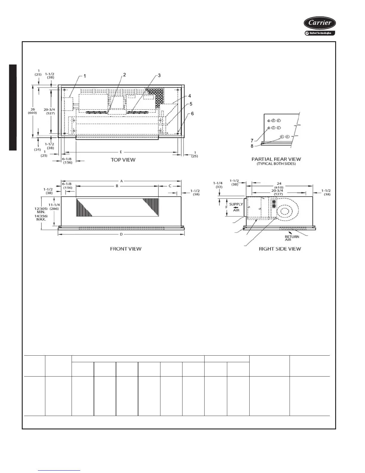
42CK HORIZONTAL CABINET UNIT WITH TELESCOPIC ACCESS PANEL,
FRONT SUPPLY, BOTTOM RETURN, AND HEATER
NOTES:
1. Right hand unit shown; left hand unit opposite.
2. Internal factory valve package and drains may not align with
cabinet knockouts.
3. Dimensions shown in inches (mm). All dimensions are
±
1
/
4
inches.
4. Bottom panel is Arctic White polyester powder coat paint.
*Unit weights are based on dry coils and minimum rows. Weights exclude packaging, valves, and other components.
UNIT
SIZE
NOM
AIRFLOW
(Cfm)
DIMENSIONS (in.) QTY/UNIT BOTTOM
RETURN
FILTER SIZE
(in.)
UNIT WEIGHT*
(lb)
ABCDEFBlowerMotor
02 200 35 16 12
3
/
4
37 32 6 1 1 10 x 21 117
03 300 35 20 8
3
/
4
37 32 6 1 1 10 x 21 122
04 400 41 26 8
3
/
4
43 38 6 2 1 10 x 27 137
06 600 53 31 15
3
/
4
55 50 7 2 1 10 x 38 152
08 800 53 38 8
3
/
4
55 50 7 2 1 10 x 38 157
10 1000 75 52 16
3
/
4
77 72 7 4 2 10 x 52 229
12 1200 75 60 8
3
/
4
77 72 7 4 2 10 x 52 243
a42-4150
LEGEND
1 — Contactor Box
2 — Strip Heater High Limit
3 — Electric Strip Heater Element
4 — Optimal L-shape Drip Lip, shipped loose
5 — Chilled/Hot Water Supply and Return Connection
6 — Resilient Mounting Grommets with
3
/
8
-in. Diameter Hole
(typically 4)
7 — Electrical Knockout,
7
/
8
-in. Diameter
8 — Drain Knockout, 1
1
/
2
-in. Diameter
9 — Stamped Return Air Grille and 1-in. Filter
10 — Condensate Drain Connection,
7
/
8
-in. OD
11 — Hinged Bottom Return Air Panel
12 — Supply Duct Collar, 1-in. OD
13 — Drain Pan
Base unit dimensions (cont)

 Loading...


