11
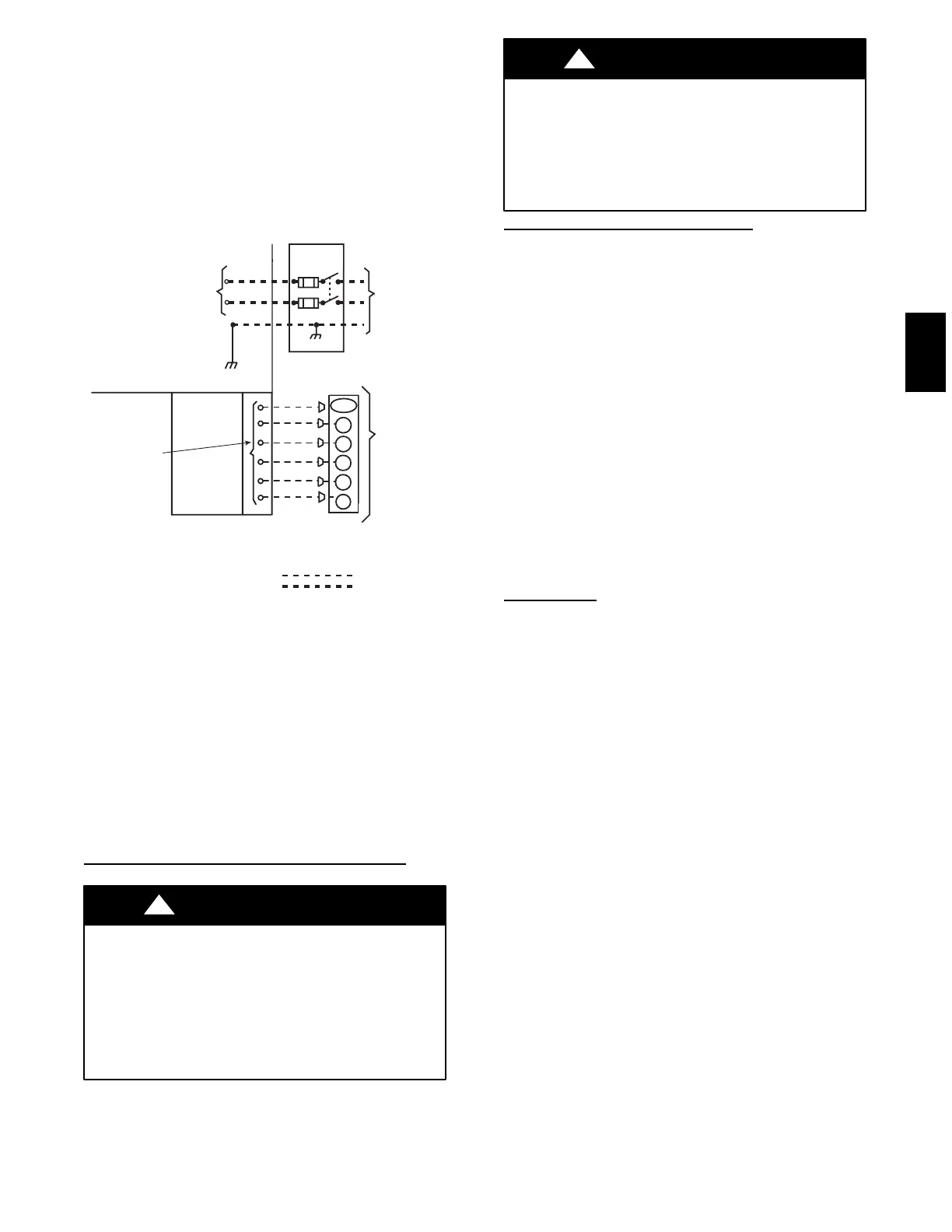
See unit wiring label and Fig. 11 for reference when making high
voltage connections. Proceed as follows to complete the high
voltage connections to the unit.
Single phase units:
1. Run the high--voltage (L1, L2) and ground leads into the
control box.
2. Connect ground lead to chassis ground connection.
3. Connect L1 to pressure lug connection 11 of the
compressor contactor.
4. Connect L2 to pressure lug connection 23 of the
compressor contactor.
POWER
SUPPLY
FIELD-SUPPLIED
FUSED DISCONNECT
HIGH VOLTAGE
POWER LEADS
(SEE UNIT WIRING
LABEL)
GND
CONTROL BOX
SPLICE BOX
LOW-VOLTAGE
POWER LEADS
(SEE UNIT
WIRING LABEL)
YEL(Y)
GRN(G)
RED(R)
BRN(C)
THERMOSTAT
(TYPICAL)
LEGEND
Field Control-Voltage Wiring
Field High-Voltage Wiring
BLK(DH)
DHUM
Y
G
R
C
W1
WHI(W1)
C01026
Fig. 11 -- High and Control--Voltage Connections
Three--phase units:
1. Run the high--voltage (L1, L2, L3) and ground leads into
the control box.
2. Connect ground lead to chassis ground connection.
3. Locate the black and yellow wires connected to the lines
side of the contactor.
4. Connect field L1 to black wire on connection 11 of the
compressor contactor.
5. Connect field wire L2 to yellow wire on connection 13 of
the compressor contactor.
6. Connect field wire L3 to Blue wire from compressor.
SPECIAL PROCEDURES FOR 2 0 8--V OPERATION
ELECTRICAL SHOCK HAZARD
Failure to follow this warning could result in personal injury
or death.
Make surethepower supplyto the unit isswitched OFF before
making any wiring changes. With disconnect switch open,
move yellow wire from transformer (3/16 in.) terminal
marked 230 to terminal marked 200. This retaps transformer
to primary voltage of 208 vac.
!
WARNING
ELECTRICAL SHOCK FIRE/EXPLOSION HAZARD
Failure to follow this warning could result in personal injury
or death and property damage.
Beforemaking any wiring changes, make sure thegas supply
is switched off first. Then switch off the power supply to the
unit and install lockout tag.
!
WARNING
CONTROL VOLTAGE CONNECTIONS
Do not use any type of power--stealing thermostat. Unit control
problems may result.
Use no. 18 American Wire Gage (AWG) color--coded, insulated
(35 C minimum) wires to make the control voltage connections
between the thermostat and the unit. If the thermostat is located
more than 100 ft from the unit (as measured along the control
voltage wires), use no. 16 AWG color--coded, insulated (35 C
minimum) wires.
Remove knockout hole located in the heat section panel adjacent
to the service access panel. Remove the rubber grommet from the
installer’s packet and install grommet in the knockout opening.
Provide a drip loop before running wire through panel. Run the
low--voltage leads from the thermostat, through the inlet hole, and
into unit low--voltage splice box. Locate 18--gage wires leaving
control box. These low--voltage connection leads can be
identified by colors (See Fig. 11). Ensure the leads are long
enough to be routed into the low--voltage splice box (located
below right side of control box). Route leads through hole in
bottom of control box and make low--voltage connections (See
Fig. 11). Secure all cut wires, so that they do not interfere with
operation of unit.
Easy Select
t -- 48XP
EASY SELECTt CONFIGURATION TAPS FOR 48XP
Easy Select taps are used by the installer to configure a system.
The ECM motor uses the selected taps to modify its operation to
a pre--programmed table of airflows.
The unit must be configured to operate properly with system
components with which it is installed. To successfully configure a
basic system (see information printed on circuit board label
located next to select pins), move the 6 select wires to the pins
which match the components used (See Fig. 12).
48XP