25
EASY SELECT
HEATER/MOTOR
GAS HEAT / CFM
130
1800
SEC1 SEC 2
J1
AC/HP SIZE
060 048 042 036
AC
HP-COMFORT
HP-EFF
NOM HI
ENH
LO
SYSTEM TYPE
AC/HP CFM ADJUST
ON/OFF DELAY
CONTINUOUS FAN
MED HI YELLO
AUX1 HUM1
AUX2
24V AC
GR Y
HUM2
YEL
WHT
BLK
ORN
BLU
VIO
115
1600
090
1250
0
90
30
90
0
0
060
1000
TM
J2
D
H
R
W
1
W
2
Y
1
Y/ Y
2
G
O
C
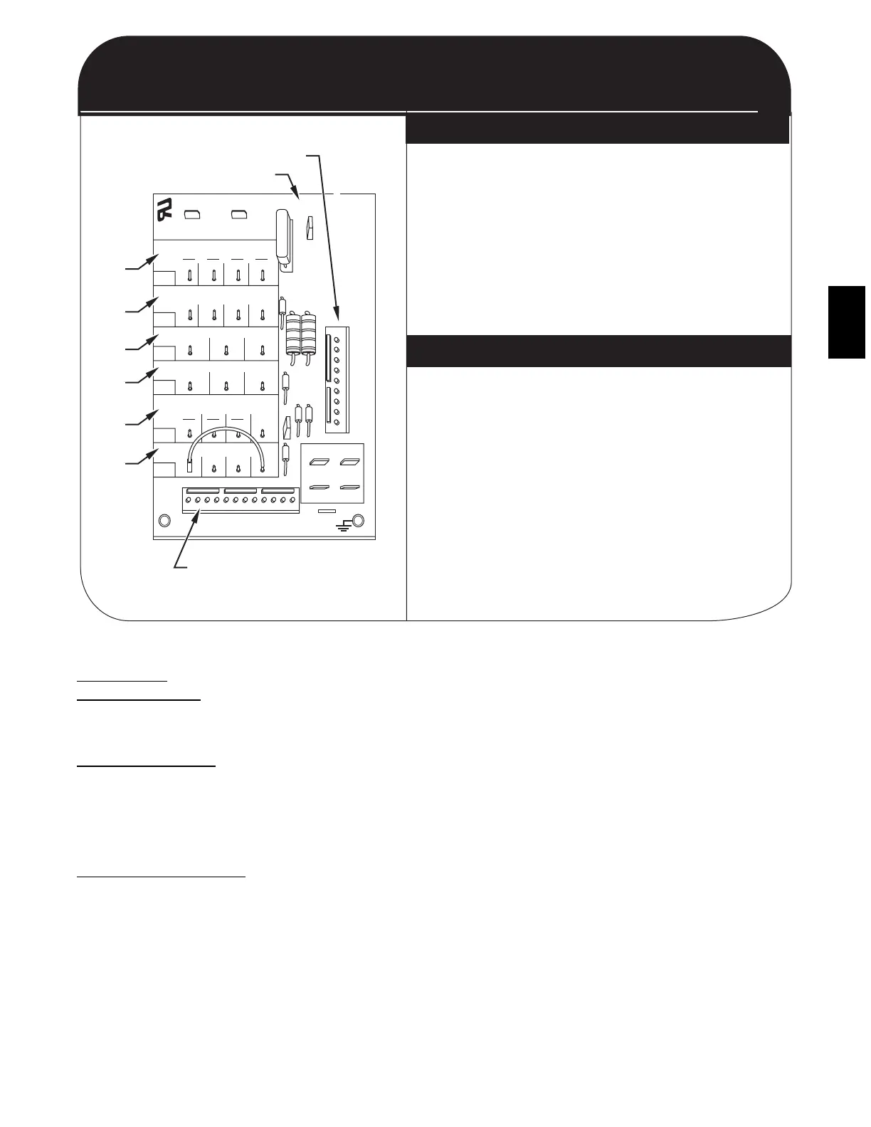
QUICK REFERENCE GUIDE
SET-UP INSTRUCTIONS FOR EASY SELECT BOARD
(SUPER HUMIDITY CONTROL IN COOLING)
EASY SELECT BOARD
THERMIDISTAT CONTROL SETTINGS
9 PIN CONNECTOR
ECM PRINTED CIRCUIT BOARD
12 PIN CONNECTOR
A
B
C
D
E
F
1. Configuration Taps
(See Installation Instructions, for detailed description)
A. HEAT RANGE - Set for gas heat size
(EX: 090 for unit 048090---)
B. AC/HP SIZE - Set for size of outdoor unit (Cooling Size)
C. SYSTEM TYPE - Select "AC" for Gas Package Units
D. AC/HP CFM ADJUST - Select "NOM"
E. ON/OFF DELAY - Do not use "ENH" for this unit
F. CONTINUOUS FAN - Select desired speed
2. Remove Jumper J1 to activate all dehumidify modes
3. Complete wiring and install outdoor temperature
sensor according to Installation Instructions
1. Set "DIP Switches" - Set the dip switches (back of
Thermidistat Control Board) appropriately for specific
system being installed.
2. Thermidistat Control Configurations
(See Thermidistat Control Installation Instructions for detailed description)
* Option 5 (Variable Speed Indoor Motor) - Set to ON
* Option 7 (Super Dehumidify) - Set to ON
* Option 17 - Select Programmable or non-programmable mode.
3. Set desired humidity level on fron of Thermidistat
(50 to 55 % RH recommended). For dehumidification in
cooling, both "dhu" and "cool" must be displayed.
C01034G
ECM ID Blower Motor--quick Reference Guide
PURON
ITEMS
METERING DEVICE
(Thermostatic Expansion Valve )
This metering device is a hard shutoff, balance port TXV. The
TXV maintains a constant superheat at the evaporator exit
resulting in higher overall system efficiency.
PRESSURE SWITCHES
Pressure switches are protective devices wired into control circuit
(low voltage). They shut off compressor if abnormally high or
low pressures are present in the refrigeration circuit. These
pressure switches are specifically designed to operate with Puron
(R--410A) systems. R--22 pressure switches must not be used as
replacements for the Puron (R--410A) system.
LOSS OF CHARGE SWITCH
This switch is located on the liquid line and protects against low
suction pressures caused by such events as loss of charge, low
airflow across indoor coil, dirty filters, etc. It opens on a pressure
drop at about 20 psig. If system pressure is above this, switch
should be closed. To check switch:
1. Turn off all power to unit.
2. Disconnect leads on switch.
3. Apply ohm meter leads across switch. You should have
continuity on a good switch.
NOTE: Because these switches are attached to refrigeration
system under pressure, it is not advisable to remove this device
for troubleshooting unless you are reasonably certain that a
problem exists. If switch must be removed, remove and recover
all system charge so that pressure gauges read 0 psi. Never open
system without breaking vacuum with dry nitrogen.
HIGH--PRESSURE SWITCH
The high--pressure switch is located in the discharge line and
protects against excessive condenser coil pressure. It opens at 610
psig.
High pressure may be caused by a dirty outdoor coil, failed fan
motor, or outdoor air recirculation. To check switch:
1. Turn off all power to unit.
2. Disconnect leads on switch.
3. Apply ohm meter leads across switch. You should have
continuity on a good switch.
COPELAND SCROLL COMPRESSOR (PURON
REFRIGERANT)
The compressor used in this product is specifically designed to
operate with Puron (R--410A) refrigerant and cannot be
interchanged.
The compressor is an electrical (as well as mechanical) device.
Exercise extreme caution when working near compressors. Power
should be shut off, if possible, for most troubleshooting
techniques. Refrigerants present additional safety hazards.
48XP