17
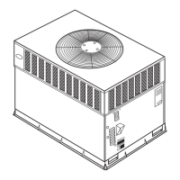
AUXILIARY LIMIT SWITCH (ROLLOUT)
The function of the switch is to close the main gas valve in the
event of flame rollout. The switch is located above the main
burners. When the temperature at the auxiliary switch reaches the
maximum allowable temperature, the R control circuit trips,
closing the gas valve and stopping gas flow to the burners. The
indoor (evaporator) fan motor (IFM) and induced draft motor
continue to run until switch is reset. The IGC LED will display
FAULT CODE 7.
Step 4 — START--UP COOLING AND MAKE
ADJUSTMENTS
UNIT DAMAGE HAZARD
Failure to follow this warning could result in unit component
damage.
Complete the required procedures given in the Pre--Start--Up
section before starting the unit. Do not jumper any safety
devices when operating the unit. Do not operate the
compressor when the outdoor temperature is below 55_F
(unless accessory low--ambient kit is installed). Do not
rapid--cycle the compressor. To prevent compressor damage
allow 5 minutes between “on” cycles.
!
WARNING
CHECKING COOLING CONTROL OPERATION
Start and check the unit for proper cooling control operation as
follows:
1. Place room thermostat SYSTEM switch in OFF position.
Observe that blower motor starts when FAN switch is
placed in ON position and shuts down when FAN switch
is placed in AUTO. position.
2. Place SYSTEM switch in COOL position and FAN switch
in AUTO. position. Set cooling control below room
temperature. Observe that compressor, condenser fan, and
evaporator blower motors start. Observe that cooling cycle
shuts down when control setting is satisfied. The
evaporator fan will continue to run for the time selected on
the Easy Select board.
3. When using an auto--changeover room thermostat, place
both SYSTEM and FAN switches in AUTO positions.
Observe that unit operates in Heating mode when
temperature control is set to “call for heating” (above room
temperature) and operates in Cooling mode when
temperature control is set to “call for cooling” (below
room temperature).
Table 3 – Heating Inputs
HEATING
INPUT (BTUH)*
NUMBER OF
ORIFICES
GAS SUPPLY PRESSURE (IN. WC)
MANIFOLD PRESSURE (IN. WC)
Natural Propane†
Min Max Min Max Natural Propane†
40,000 2 4.0 13.0 4.0 13.0 3.5 3.5
60,000 2 4.0 13.0 4.0 13.0 3.5 3.5
90,000 3 4.0 13.0 4.0 13.0 3.5 3.4
115,000 3 4.0 13.0 4.0 13.0 3.5 3.7
130,000 3 4.0 13.0 4.0 13.0 3.5 3.5
* When a unit is converted to propane, different size orifices must be used. See separate, natural--to--propane conversion kit instructions.
† Based on altitudes from sea level to 2000 ft above sea level. For altitudes above 2000 ft, reduce input rating 4 percent for each additional 1000 ft above sea level.
In Canada, from 2000 ft above sea level to 4500 ft above sea level, de--rate the unit 10 percent.
Table 4 – Air Delivery (CFM) at Indicated Temperature Rise and Rated Heating Input
HEATING
INPUT
(BTUH)
TEMPERATURE RISE °F
20 25 30 35 40 45 50 55 60 65 70
40,000 1500 1200 1000 857 750 667 600 545 500 — —
60,000 2250 1800 1500 1286 1125 1000 900 818 750 692 —
90,000 — — 2250 1929 1688 1500 1350 1227 1125 1038 964
115,000 — — — 2464 2156 1917 1725 1568 1438 1327 1232
130,000 — — — 2786 2438 2167 1950 1773 1625 1500 —
NOTE: Dashed areas do not fall within the approved temperature rise range of the unit.
Table 5 – LED Indications
ERROR CODE LED INDICATION
Normal Operation On
Hardware Failure Off
Fan On/Off Delay Modified 1Flash
Limit Switch Fault 2Flashes
Flame Sense Fault 3Flashes
Four Consecutive Limit Switch Faults 4Flashes
Ignition Lockout Fault 5Flashes
I n d u c e d --- D r a f t M o t o r F a u l t 6Flashes
Rollout Switch Fault 7Flashes
Internal Control Fault 8Flashes
Safety Critical Code Fault 9Flashes
NOTES:
1. There is a 3 ---sec. pause between error code displays.
2. If more than one error code exists, all applicable error codes will be displayed in numerical sequence.
3. This chart is on the wiring diagram located inside the burner access panel.
Table 6 – Filter Pressure Drop (in. wc)
FILTER
SIZE
CFM
500 600 700 800 900 1000 1100 1200 1300 1400 1500 1600 1700 1800 1900 2000 2100 2200 2300
20X20X1 0.05 0.07 0.08 0.10 0.12 0.13 0.14 0.15 — — — — — — — — — — —
20X24X1 — — — — 0.09 0.10 0.11 0.13 0.14 0.15 0.16 — — — — — — — —
24X30X1 — — — — — — — 0.07 0.08 0.09 0.10 0.11 0.12 0.13 0.14 0.15 0.16 0.17 0.18
48XP