16
4. Divide number of seconds in Step 3 into 3600 (number of
seconds in one hr).
5. Multiply result of Step 4 by the number of cu ft shown for
one revolution of test dial to obtain ft
3
of gas flow per hr.
6. Multiply result of Step 5 by Btu heating value of gas to
obtain total measured input in Btuh. Compare this value
with heating input shown in Table 3 (Consult the local gas
supplier if the heating value of gas is not known).
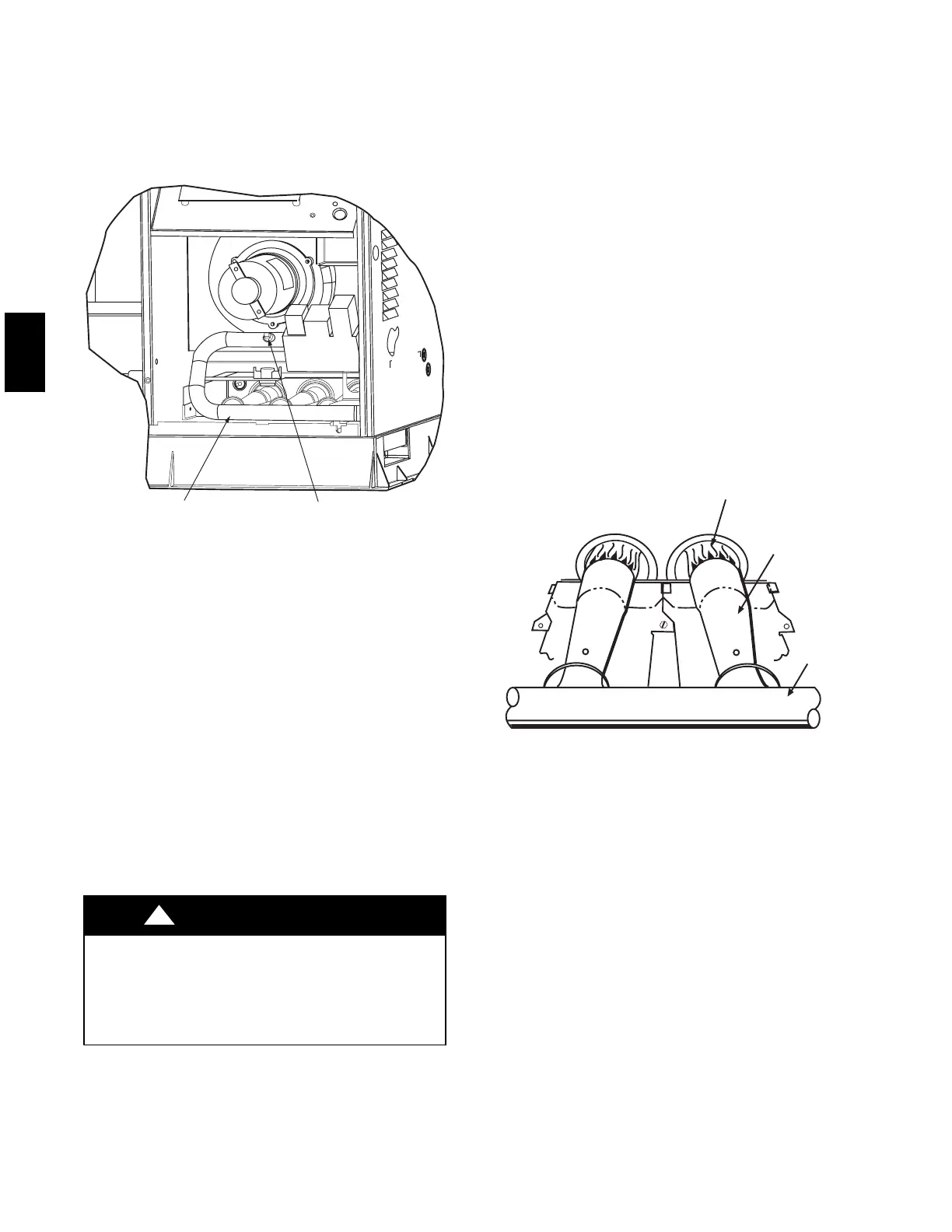
MANIFOLD PIPE PLUG
C99019
Fig. 16 -- Burner Assembly
EXAMPLE: Assume that the size of test dial is 1 ft
3
, one
revolution takes 32 sec., and the heating value of the gas is 1050
Btu/ft3. Proceed as follows:
1. 1. 32 sec. to complete one revolution.
2. 3600 ÷ 32 = 112.5.
3.112.5x1=112.5ft
3
of gas flow/hr.
4. 112.5 x 1050 = 118,125 Btuh input.
If the desired gas input is 115,000 Btuh, only a minor change in
the manifold pressure is required.
Observe manifold pressure and proceed as follows to adjust gas
input:
1. Remove cover screw over regulator adjustment screw on
gas valve.
2. Turn regulator adjustment screw clockwise to increase gas
input, or turn regulator adjustment screw counterclockwise
to decrease input. Manifold pressure must be between 3.4
and 3.6 in. wc. Unsafe operation of the unit may result if
manifold pressure is outside this range. Personal injury or
unit damage may result.
FIRE AND UNIT DAMAGE HAZARD
Failure to follow this warning could result in personal injury
or death and/or property damage.
Unsafe operation of the unit may result if manifold pressure
is outside this range.
!
WARNING
3. Replace cover screw cap on gas valve.
4. Turn off gas supply to unit. Remove manometer from
pressure tap and replace pipe plug on gas valve. Turn on
gas to unit and check for leaks.
Measure Manifold Pressure (Propane Units)
The main burner orifices on a propane gas unit are sized for the
unit rated input when the manifold pressure reading matches the
level specified in Table 3.
Proceed as follows to adjust gas input on a propane gas unit:
1. Turn off gas to unit.
2. Remove pipe plug on manifold and connect manometer
(See Fig. 16).
3. Turn on gas to unit.
4. Remove cover screw over regulator adjustment screw on
gas valve.
5. Adjust regulator adjustment screw to the correct manifold
pressure, as specified in Table 3. Turn adjusting screw
clockwise to increase manifold pressure, or turn adjusting
screw counterclockwise to decrease manifold pressure.
6. Replace cover screw.
7. Turn off gas to unit. Remove manometer from pressure
tap. Replace pipe plug on gas valve, then turn on gas to
unit. Check for leaks.
CHECK BURNER FLAME
With burner access panel removed, observe the unit heating
operation. Watch the burner flames to see if they are light blue
and soft in appearance, and that the flames are approximately the
same for each burner. Propane will have blue flame with yellow
tips (See Fig. 17). Refer to the Maintenance section for
information on burner removal.
MANIFOLD
BURNER
BURNER FLAME
C99021
Fig. 17 -- Monoport Burner
AIRFLOW AND TEMPERATURE RISE
The heating section for each size unit is designed and approved
for heating operation within the temperature--rise range stamped
on the unit rating plate. Table 4 shows the approved temperature
rise range for each heating input, and the air delivery cfm at
various temperature rises. The heating operation airflow must
produce a temperature rise that falls within the approved range.
Refer to Indoor Airflow and Airflow Adjustments section to
adjust heating airflow when required.
LIMIT SWITCHES
Normally closed limit switch (LS) completes the control circuit
through the thermostat R circuit. Should the leaving--air
temperature rise above the maximum allowable temperature, the
limit switch opens and the R control circuit “breaks.” Any
interruption in the R control circuit instantly closes the gas valve
and stops gas flow to the burners and pilot. The blower motor
continues to run until LS resets.
When the air temperature at the limit switch drops to the
low--temperature setting of the limit switch, the switch closes and
completes the R control circuit. The electric--spark ignition
system cycles and the unit returns to normal heating operation.
48XP