4
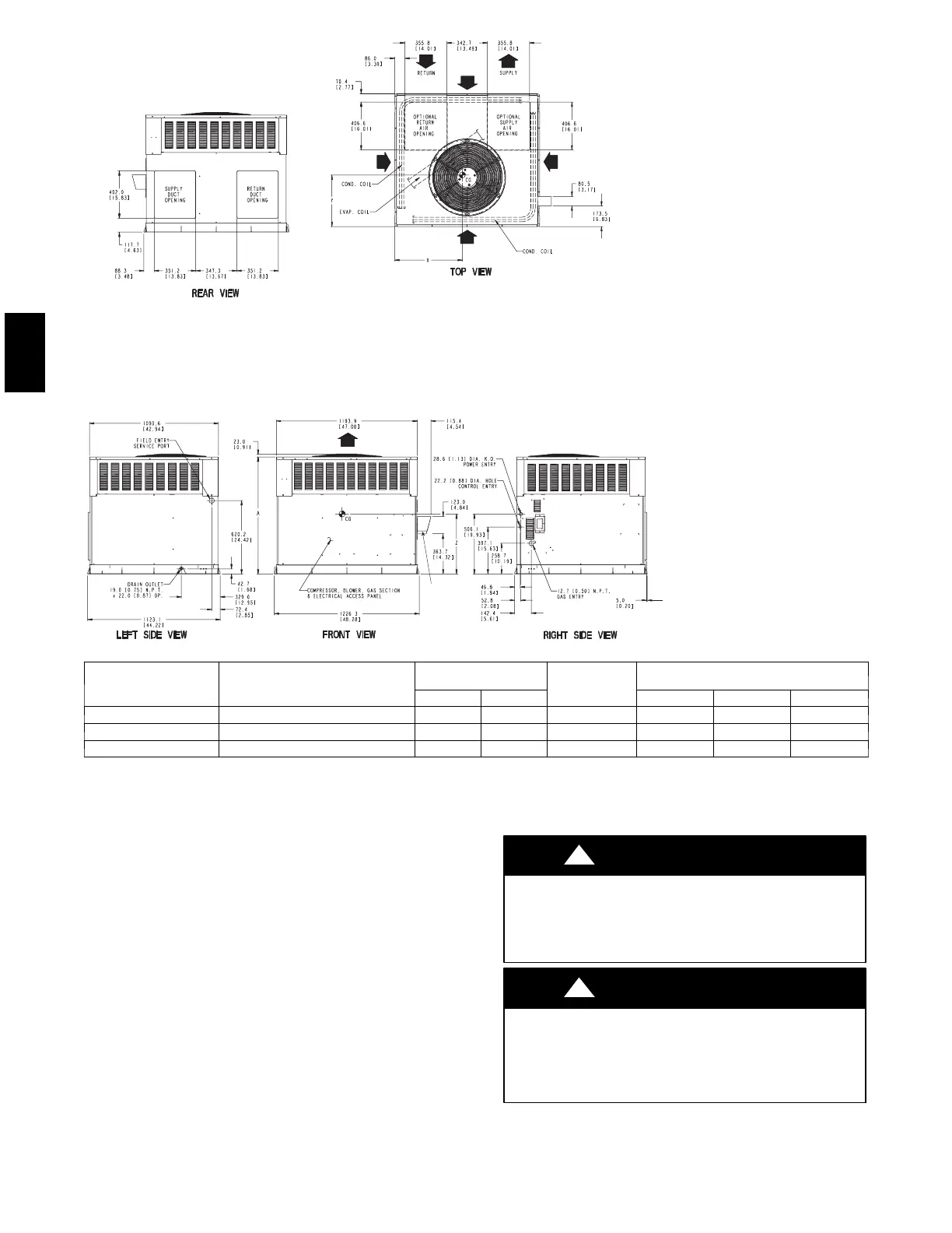
REQUIRED CLEARANCE FOR OPERATION AND SERVICING
in. [mm]
EVAP. COIL ACCESS SIDE..............................................................36.00 [914.0]
POWER ENTRY SIDE......................................................................36.00 [914.0]
(EXCEPT FOR NEC REQUIREMENTS)
UNIT TOP.........................................................................................36.00 [914.0]
SIDE OPPOSITE DUCTS ................................................................36.00 [914.0]
DUCT PANEL ...................................................................................12.00 [304.8] *
*MINIMUM DISTANCES: IF UNIT IS PLACED LESS THAN 12.00 [304.8] FROM
WALL SYSTEM, THEN SYSTEM PERFORMANCE MAYBE COMPROMISE.
REQUIRED CLEARANCE TO COMBUSTIBLE MATL.
in. [mm]
TOP OF UNIT...................................................................................14.00 [355.6]
DUCT SIDE OF UNIT.........................................................................2.00 [50.8]
SIDE OPPOSITE DUCTS ................................................................14.00 [355.6]
BOTTOM OF UNIT .............................................................................0.50 [12.7]
ELECTRIC HEAT PANEL .................................................................36.00 [914.4]
NEC. REQUIRED CLEARANCES.
MILLIMETERS [IN.]
BETWEEN UNITS, POWER ENTRY SIDE ....................................42.00 [1066.8]
UNIT AND UNGROUNDED SURFACES, POWER ENTRY SIDE ...36.00 [914.0]
UNIT AND BLOCK OR CONCRETE WALLS AND OTHER
GROUNDED SURFACES, POWER ENTRY SIDE.........................42.00 [1066.8]
FLUE HOOD
C99074
UNIT
ELECTRICAL
CHARACTERISTICS
UNIT WEIGHT
UNIT HEIGHT
IN. [MM]
“A”
CENTER OF GRAVITY
IN. [MM]
lb kg X Y Z
48XP042--060/090 208/230--1--60, 208/230--3--60 440 200 42.98 [1091.7] 21.0 [533.4] 20.5 [520.7] 16.6 [421.6]
48XP048--090/115/130 208/230--1--60, 208/230--3--60 463 210 44.98 [1142.5] 19.5 [495.3] 21.3 [539.8] 18.0 [457.2]
48XP060--090/115/130 208/230--1--60, 208/230--3--60 499 226 46.98 [1193.3] 21.0 [533.4] 20.0 [508.0] 17.6 [447.0]
Fig. 3 -- 48XP042--060 Unit Dimensions
Step 5 — Rig and Place Unit
Rigging and handling of this equipment can be hazardous for
many reasons due to the installation location (roofs, elevated
structures, etc.).
Only trained, qualified crane operators and ground support staff
should handle and install this equipment.
When working with this equipment, observe precautions in the
literature, on tags, stickers, and labels attached to the equipment,
and any other safety precautions that might apply.
Use spreader bars or crate top when rigging the unit. The units
must be rigged for lifting (See Fig. 6). Refer to Table 1 for
operating weight. Use extreme caution to prevent damage when
moving the unit. Unit must remain in an upright position during
all rigging and moving operations. The unit must be level for
proper condensate drainage; therefore, the ground--level pad or
accessory roof curb must be level before setting the unit in place.
When a field--fabricated support is used, be sure that the support
is level and properly supports the unit. Lifting point should be
directly over the center of gravity for the unit.
UNIT FALLING HAZARD
Failure to follow this warning could result in personal
injury or death.
Never stand beneath rigged units or lift over people.
!
WARNING
PERSONAL INJURY HAZARD
Failure to follow this warning could result in personal
injury or death.
Never exceed 200 lbs. per bracket lifting force.
!
WARNING
48XP