4
OUTSIDE AIR HOOD
Outside air hood inlet screens are permanent aluminum-mesh type
filters. Check these for cleanliness. Remove the screens when
cleaning is required. Clean by washing with hot low-pressure wa-
ter and soft detergent and replace all screens before restarting the
unit. Observe the flow direction arrows on the side of each filter
frame.
ECONOMIZER INLET AIR SCREEN
This air screen is retained by filter clips under the top edge of the
hood. (See Fig. 3.)
Fig. 3 — Filter Installation
To remove the filter, open the filter clips. Re-install the filter by
placing the frame in its track, then closing the filter clips.
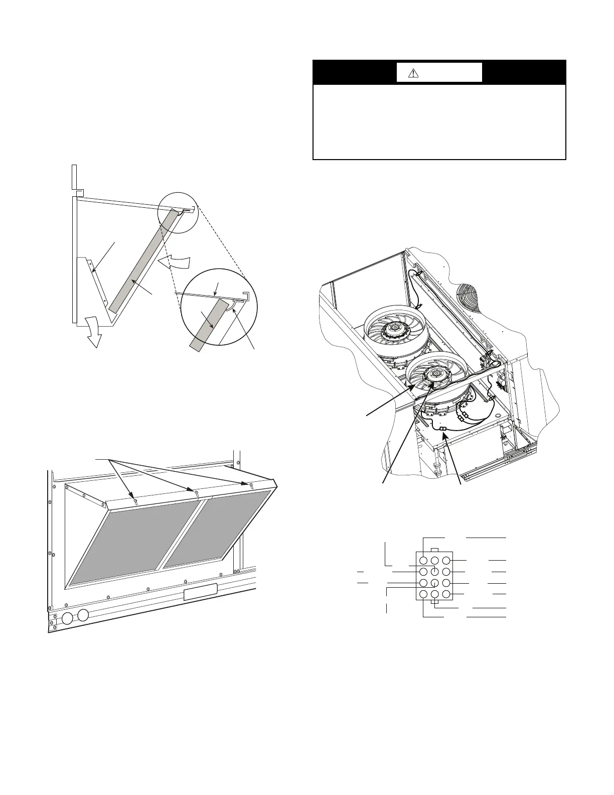
MANUAL OUTSIDE AIR HOOD SCREEN
This inlet screen is secured by a retainer angle across the top edge
of the hood. (See Fig. 4.)
Fig. 4 — Screens Installed on Outdoor-Air Hood
To remove the screen, loosen the screws in the top retainer and slip
the retainer up until the filter can be removed. Re-install by plac-
ing the frame in its track, rotating the retainer back down, and
tightening all screws.
SUPPLY FAN (BLOWER) SECTION
Supply Fan (Direct-Drive)
All FC units have the EcoBlue™ direct drive vane axial fan sys-
tem. The fan is driven by an ECM motor with speed that is user set
through the Unit Control Board (UCB). Speeds are fully configu-
rable from 40% to 100% of motor’s maximum speed.
See Fig. 5 and 6.
Fig. 5 — Direct-Drive Supply Fan Assembly
Fig. 6 — ECM Motor Plug Connectors
Divider
Outside
Air
Hood
Filter
Filter Clip
Cleanable
Aluminum
Filter
Barometric
Relief
WARNING
ELECTRICAL SHOCK HAZARD
Failure to follow this warning could result in personal injury
or death.
Before performing service or maintenance operations on unit,
LOCKOUT/TAG-OUT the main power switch to unit. Elec-
trical shock and rotating equipment could cause severe injury.
Motor Plug
Fan
Assembly
ECM Motor
123
456
789
10 11 12
CTL Signal CommonSerial (R/T)
Safety Relay
Power L1
Power L2
Power L3
10 vdc Source
0-10 vdc signal
Earth Ground
Safety Relay
PWM signal
WHITE
BLACK
YELLOW
BLUE
YEL/GRN
RED
GRAY
RED
PINK
ORANGE
VIOLET
 Loading...


