5
EVALUATING MOTOR SPEED
The direct drive ECM blower motor uses a constant speed design.
Motor speed is controlled by a 0-10 vdc signal, where 10 vdc is
equal to motor’s maximum rpm.
SELECTING FAN SPEED
All units come factory set for 7.8 vdc or approximately 78% of the
motor’s maximum speed. Fan speed should be set per job specifi-
cation cfm (cubic feet per minute) and ESP (external static pres-
sure) required and per Fan speed set up label included on the unit’s
high voltage cover. In some cases, the Fan Speed Set Up label may
already include the field setting if unit was previously installed.
Check the box on the lower half of the label to see if the field volt-
age setting was filled in and if so, set fan speed to that voltage.
Otherwise see detailed instructions below.
NOTE: Fan Speed Set-Up is for full load airflow. If the unit has
multiple stages of cooling, low cool and ventilation may operate at
lower fan rpms. This offset is factory set and controlled by the
UCB. If fan speed verification is being done with a strobe, fan
speed should be verified in all unit operation modes.
Units with Electro-mechanical controls
The Fan Speed set up controls are located on the lower section of
the Unit Control Board (UCB). See Fig. 7 for location.
1. Check the job specifications for the cfm (cubic feet per
minute) and ESP (external static pressure) required.
2. Using the chart on the Fan Speed Set Up labels (see Fig. 8),
calculate the vdc from the cfm and ESP for the base.
3. If installing any accessories listed at the bottom of the Set
Up Label, add accessory vdc to base unit vdc in upper por-
tion of label.
NOTE: The Fan Speed Set Up labels are located on the High
Voltage cover in the Control Box.
4. Connect a multimeter to the vdc terminals on the UCB.
5. Set the Range Switch to either A, B, or C per the Switch
Range table.
6. Using a straight blade screwdriver turn the vdc control dial
to fine tune the vdc reading.
7. Record the reading in the Field Setting field.
NOTE: Fan set-up vdc is not affected by the operating stage of
the unit.
NOTE: For units equipped with the Humidi-MiZer option, when
replacing the UCB cut JMP 1,2 and 3 in the REHEAT/HP section
of the replacement UCB.
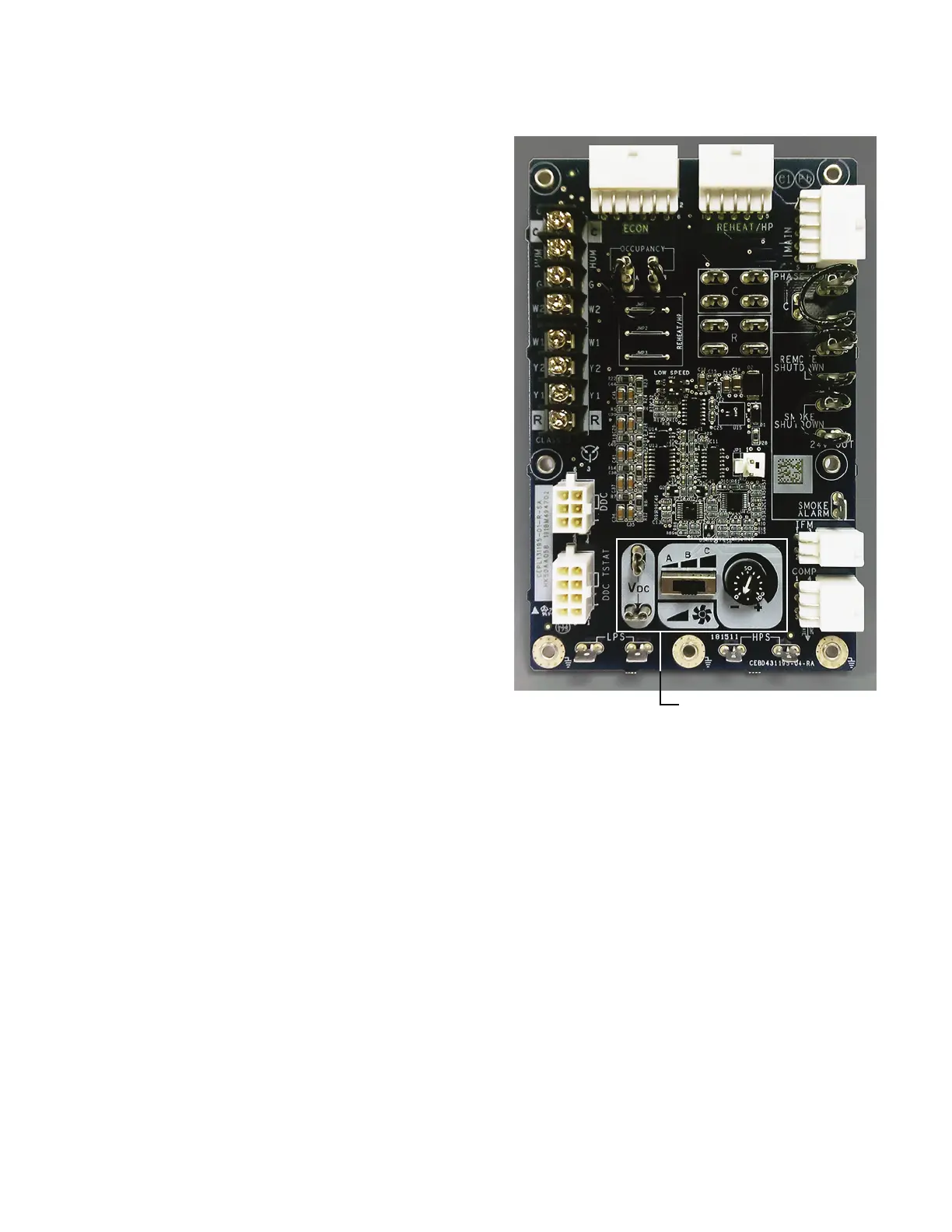
Fig. 7 — UCB Fan Speed Controls - 3-Phase Units
Fan Speed Set Up Controls
 Loading...


