6
NOTE(S):
Values in the Field Accessories section are VDC adders.
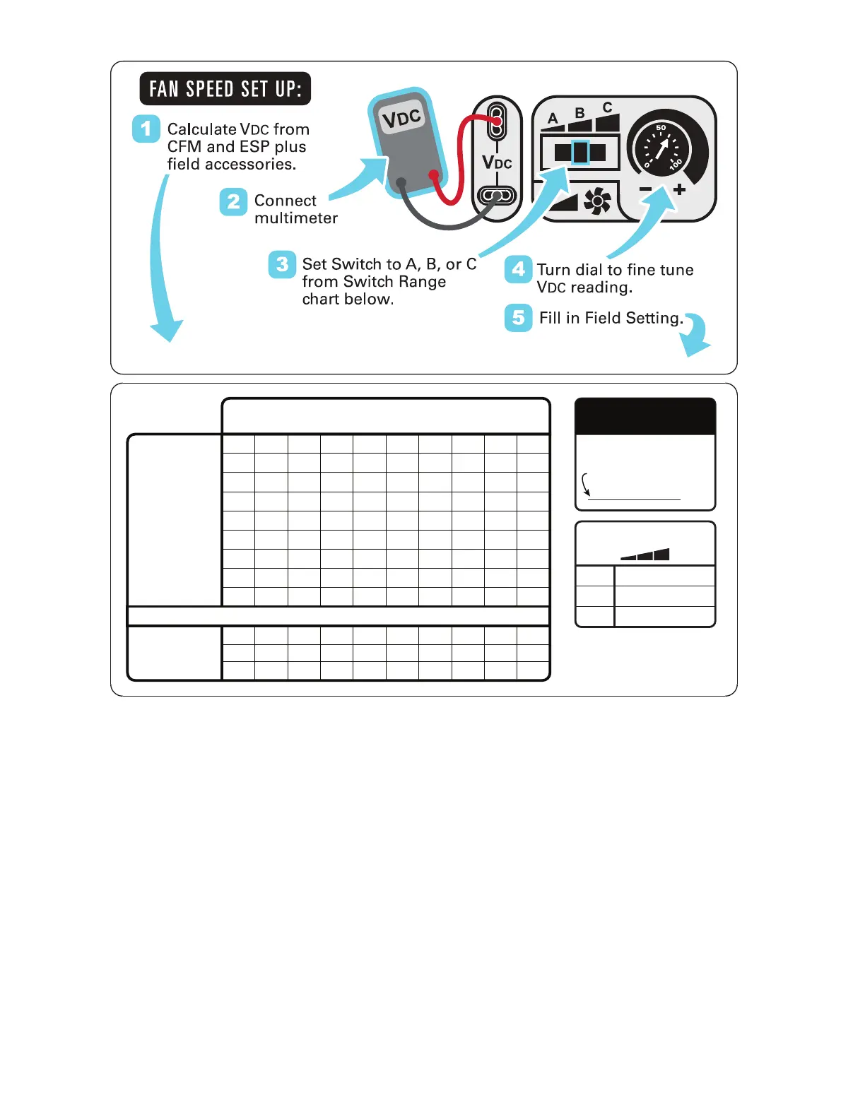
Fig. 8 — Example of Fan Speed Set Up Labels for Electro-Mechanical Controls
Units with SystemVu™ controls
On units equipped with the factory-installed SystemVu controller
the Fan Speed settings are accessed through the SystemVu inter-
face.
1. Check the job specifications for the cfm (cubic feet per
minute) and ESP (external static pressure) required.
2. Using the chart on the Fan Speed Set Up labels (see
Fig. 9), calculate the rpm from the cfm and ESP for the
base unit.
3. If installing any accessories listed at the bottom of the Set
Up Label, add accessory rpm to base unit rpm in upper
portion of label.
NOTE: The Fan Speed Set Up labels are located on the High
Voltage cover in the Control Box.
4. Press any key on the SystemVu interface to activate the
display backlight and then press the MENU key.
5. Using the UP and DOWN arrow keys highlight SET-
TINGS and then press ENTER.
6. Use the DOWN arrow key highlight the UNIT CONFIG-
URATIONS menu then press ENTER.
7. Highlight UNIT CONFIGURATIONS then press ENTER.
8. Highlight INDOOR FAN and then press ENTER.
9. Refer to the job specifications to set the following, deter-
mining the values per the rpm Calculator label (see Fig. 9).
Use the UP and DOWN arrow keys and the BACK key to
set the values. Press ENTER after setting each value to
continue to the next selection.
• IDF VENT SPD
• IDF HEAT SPD
• IDF LOW COOL SPD
• IDF HIGH SPD
• IDF FREE COOL SPD
For further details see the FC/GC Series Single Package Rooftop
Units with SystemVu Controller Controls, Start-up, Operation and
Troubleshooting manual.
Factory Setting:
9.0 VDC
Field Setting:
V
Switch Range:
A
B
C
B
A
C
Field Accessories:
ESP in. wg
V
DC
Calculator
CFM
0.2
5.6
6.0
6.4
6.8
7.2
7.6
8.0
8.5
8.9
6000
6500
7000
7500
8000
8500
9000
9500
10000
0.4
0.4
6.1
6.4
6.8
7.2
7.6
8.0
8.4
8.8
9.2
0.4
0.6
6.5
6.8
7.2
7.5
7.9
8.3
8.7
9.1
0.4
0.8
6.9
7.2
7.6
7.9
8.2
8.6
9.0
0.4
1.0
7.3
7.6
7.9
8.2
8.6
0.4
1.2
7.6
7.9
8.2
8.6
0.4
1.4
8.0
8.3
8.6
0.4
1.6 1.8 2.0
8.3
0.4 0.4 0.4Economizer
UNIT MODEL NUMBER
4.1 - 7.5
6.9 - 8.7
7.7 - 10.0
8.6
8.9
8.9
9.28.9
9.2
9.6
9.5
9.2
9.5
8.6
8.9
9.2
9.5
8.9
9.2
9.5
9.7
9.8
9.8
9.8
8.9
9.3
9.6 9.9
9.3
9.79.4 10.0
Record field setting here
*
* Overlap in A, B, C switch range
designed for maximum field
adjustment potential. For example
7.2 can be set at either A or B.
 Loading...


