8
TROUBLESHOOTING THE ECM MOTOR
EcoBlue™ motors are designed with several built-in protections
included in the motor software. If the motor detects a fault it will
safely shut down. See Table 4, “Supply Fan Motor Logic and
Safety Relays” on page 36 for a complete list.
Troubleshooting the motor requires a voltmeter.
1. Disconnect main power to the unit.
2. Disconnect motor plug in supply section of the unit.
3. Restore main unit power.
4. Check for proper line voltage at motor power leads Black
(PL1-1), Yellow (PL1-2), and Blue (PL1-3). Blue is only
present on 3-phase motors. See the following table.
5. Disconnect main power.
6. Reconnect motor plug in supply section of unit.
7. Restore main power.
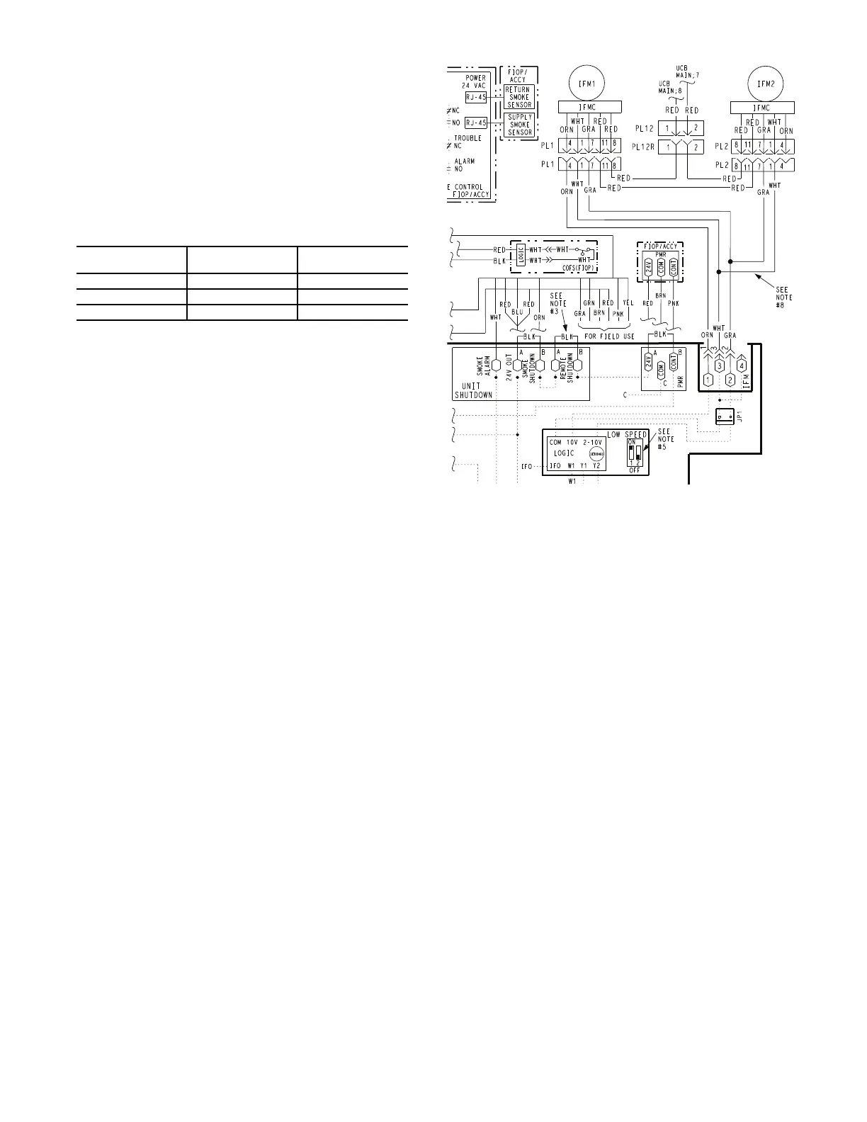
8. Check for proper motor control voltage signal of 9.7 vdc to
10.3 vdc at IFM-1 and IFM-3 on Unit Control Board
(UCB). See Fig. 10.
9. Using a jumper wire from unit control terminals R to G,
engage motor operation.
10. Verify control signal from user speed selection switch by
placing voltmeter taps in provided terminals marked vdc.
Signal should be between 3.8 vdc and 10.3 vdc.
11. If the motor does not start and run, remove the fan assembly
and replace the motor with one having the same part num-
ber. Do not substitute with an alternate design motor as the
voltage/speed programming will not be the same as that on
an original factory motor.
Fig. 10 — Supply Fan Control Wiring Diagram
50FC UNIT
VOLTAGE
MOTOR VOLTAGE MIN-MAX VOLTS
208/230 230 187-253
460 460 360-506
575 575 517-633
 Loading...


