9
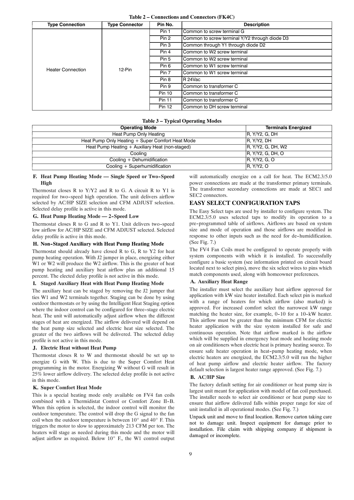
Table 2 – Connections and Connectors (FK4C)
Type Connection Type Connector Pin No. Description
Heater Connection 12-Pin
Pin 1 Common to screw terminal G
Pin 2 Common to screw terminal Y/Y2 through diode D3
Pin 3 Common through Y1 through diode D2
Pin 4 Common to W2 screw terminal
Pin 5 Common to W2 screw terminal
Pin 6 Common to W1 screw terminal
Pin 7 Common to W1 screw terminal
Pin 8 R 24Vac
Pin 9 Common to transformer C
Pin 10 Common to transformer C
Pin 11 Common to transformer C
Pin 12 Common to DH screw terminal
Table 3 – Typical Operating Modes
Operating Mode Terminals Energized
Heat Pump O n ly Heating R, Y/Y2, G, DH
Heat Pump O n ly Heating + Super Comfort Heat Mode R, Y/Y2, DH
Heat Pump Heating + Auxiliary Heat (non-staged) R, Y/Y2, G, DH, W2
Cooling R, Y/Y2, G, DH, O
Cooling + Dehumidification R, Y/Y2, G, O
Cooling + Superhumidification R, Y/Y2, O
F. Heat Pump Heating Mode — Single Speed or Two--Speed
High
Thermostat closes R to Y/Y2 and R to G. A circuit R to Y1 is
required for two--speed high operation. The unit delivers airflow
selected by AC/HP SIZE selection and CFM ADJUST selection.
Selected delay profile is active in this mode.
G. Heat Pump Heating Mode — 2--Speed Low
Thermostat closes R to G and R to Y1. Unit delivers two--speed
low airflow for AC/HP SIZE and CFM ADJUST selected. Selected
delay profile is active in this mode.
H. Non--Staged Auxiliary with Heat Pump Heating Mode
Thermostat should already have closed R to G, R to Y2 for heat
pump heating operation. With J2 jumper in place, energizing either
W1 or W2 will produce the W2 airflow. This is the greater of heat
pump heating and auxiliary heat airflow plus an additional 15
percent. The elected delay profile is not active in this mode.
I. Staged Auxiliary Heat with Heat Pump Heating Mode
The auxiliary heat can be staged by removing the J2 jumper that
ties W1 and W2 terminals together. Staging can be done by using
outdoor thermostats or by using the Intelligent Heat Staging option
where the indoor control can be configured for three--stage electric
heat. The unit will automatically adjust airflow when the different
stages of heat are energized. The airflow delivered will depend on
the heat pump size selected and electric heat size selected. The
greater of the two airflows will be delivered. The selected delay
profile is not active in this mode.
J. Electric Heat without Heat Pump
Thermostat closes R to W and thermostat should be set up to
energize G with W. This is due to the Super Comfort Heat
programming in the motor. Energizing W without G will result in
25% lower airflow delivery. The selected delay profile is not active
in this mode.
K. Super Comfort Heat Mode
This is a special heating mode only available on FV4 fan coils
combined with a Thermidistat Control or Comfort Zone II--B.
When this option is selected, the indoor control will monitor the
outdoor temperature. The control will drop the G signal to the fan
coil when the outdoor temperature is between 10_ and 40_ F. This
triggers the motor to slow to approximately 213 CFM per ton. The
heaters will stage as needed during this mode and the motor will
adjust airflow as required. Below 10_ F., the W1 control output
will automatically energize on a call for heat. The ECM2.3/5.0
power connections are made at the transformer primary terminals.
The transformer secondary connections are made at SEC1 and
SEC2 connectors.
EASY SELECT CONFIGURATION TAPS
The Easy Select taps are used by installer to configure system. The
ECM2.3/5.0 uses selected taps to modify its operation to a
pre--programmed table of airflows. Airflows are based on system
size and mode of operation and those airflows are modified in
response to other inputs such as the need for de--humidification.
(See Fig. 7.)
The FV4 Fan Coils must be configured to operate properly with
system components with which it is installed. To successfully
configure a basic system (see information printed on circuit board
located next to select pins), move the six select wires to pins which
match components used, along with homeowner preferences.
A. Auxiliary Heat Range
The installer must select the auxiliary heat airflow approved for
application with kW size heater installed. Each select pin is marked
with a range of heaters for which airflow (also marked) is
approved. For increased comfort select the narrowest kW range
matching the heater size, for example, 0--10 for a 10--kW heater.
This airflow must be greater than the minimum CFM for electric
heater application with the size system installed for safe and
continuous operation. Note that airflow marked is the airflow
which will be supplied in emergency heat mode and heating mode
on air conditioners when electric heat is primary heating source. To
ensure safe heater operation in heat--pump heating mode, when
electric heaters are energized, the ECM2.3/5.0 will run the higher
of heat pump airflow and electric heater airflow. The factory
default selection is largest heater range approved. (See Fig. 7.)
B. AC/HP Size
The factory default setting for air conditioner or heat pump size is
largest unit meant for application with model of fan coil purchased.
The installer needs to select air conditioner or heat pump size to
ensure that airflow delivered falls within proper range for size of
unit installed in all operational modes. (See Fig. 7.)
Unpack unit and move to final location. Remove carton taking care
not to damage unit. Inspect equipment for damage prior to
installation. File claim with shipping company if shipment is
damaged or incomplete.