5
312753
T-O-D 60TX11
HH19ZA945
C9725
L145-55F
312753
T-O-D 60TX11
HH19ZA945
C9725
L145-55F
SPT
FAN
RELAY
NO
NC
5
PULL TO OPEN
WARNING
ELECTRIC SHOCK
HAZARD
DISCONNECT
REMOTE POWER
SUPPLY BEFORE
OPENING PANEL.
322861-101 REV. A
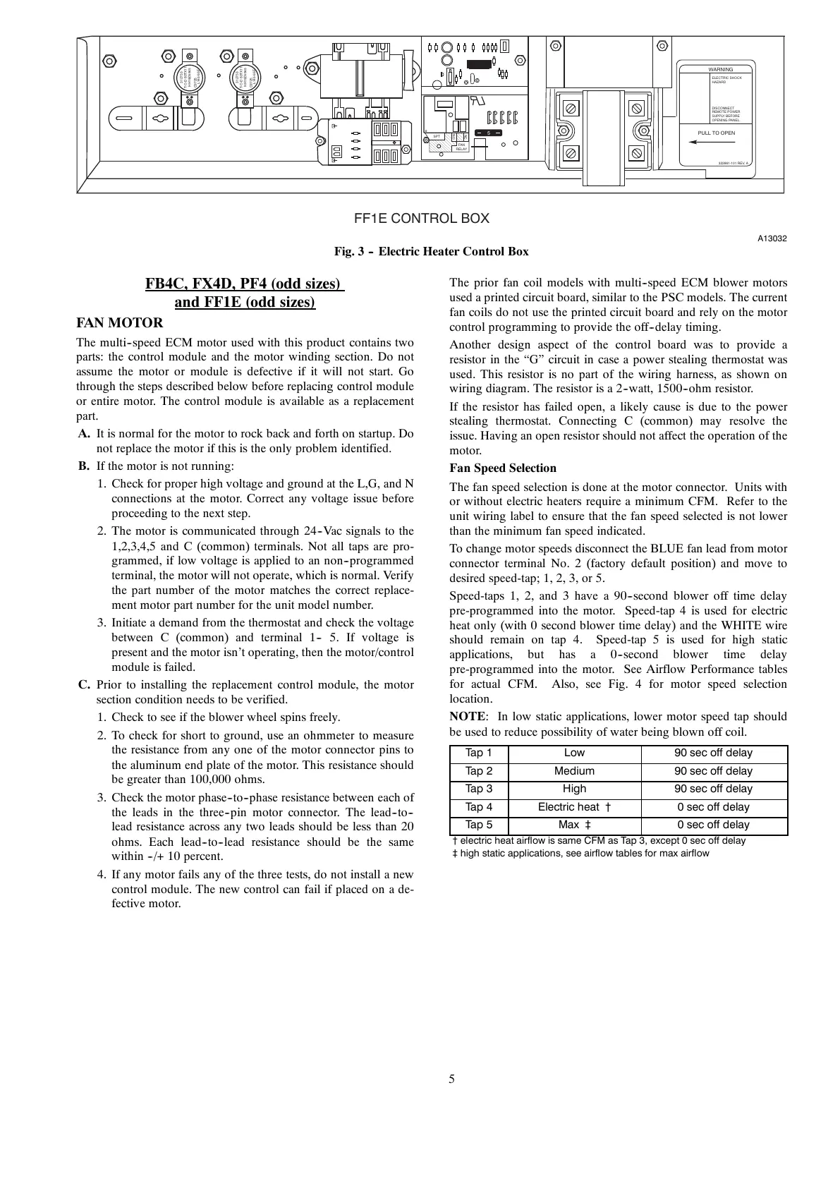
FF1E CONTROL BOX
A13032
Fig. 3 -- Electric Heater Control Box
FB4C, FX4D, PF4 (odd sizes)
and FF1E (odd sizes)
FAN MOTOR
The multi--speed ECM motor used with this product contains two
parts: the control module and the motor winding section. Do not
assume the motor or module is defective if it will not start. Go
through the steps described below before replacing control module
or entire motor. The control module is available as a replacement
part.
A. It is normal for the motor to rock back and forth on startup. Do
not replace the motor if this is the only problem identified.
B. If the motor is not running:
1. Check for proper high voltage and ground at the L,G, and N
connections at the motor. Correct any voltage issue before
proceeding to the next step.
2. The motor is communicated through 24--Vac signals to the
1,2,3,4,5 and C (common) terminals. Not all taps are pro-
grammed, if low voltage is applied to an non--programmed
terminal, the motor will not operate, which is normal. Verify
the part number of the motor matches the correct replace-
ment motor part number for the unit model number.
3. Initiate a demand from the thermostat and check the voltage
between C (common) and terminal 1-- 5. If voltage is
present and the motor isn’t operating, then the motor/control
module is failed.
C. Prior to installing the replacement control module, the motor
section condition needs to be verified.
1. Check to see if the blower wheel spins freely.
2. To check for short to ground, use an ohmmeter to measure
the resistance from any one of the motor connector pins to
the aluminum end plate of the motor. This resistance should
be greater than 100,000 ohms.
3. Check the motor phase--to--phase resistance between each of
the leads in the three--pin motor connector. The lead--to--
lead resistance across any two leads should be less than 20
ohms. Each lead--to--lead resistance should be the same
within --/+ 10 percent.
4. If any motor fails any of the three tests, do not install a new
control module. The new control can fail if placed on a de-
fective motor.
The prior fan coil models with multi--speed ECM blower motors
used a printed circuit board, similar to the PSC models. The current
fan coils do not use the printed circuit board and rely on the motor
control programming to provide the off--delay timing.
Another design aspect of the control board was to provide a
resistor in the “G” circuit in case a power stealing thermostat was
used. This resistor is no part of the wiring harness, as shown on
wiring diagram. The resistor is a 2--watt, 1500--ohm resistor.
If the resistor has failed open, a likely cause is due to the power
stealing thermostat. Connecting C (common) may resolve the
issue. Having an open resistor should not affect the operation of the
motor.
Fan Speed Selection
The fan speed selection is done at the motor connector. Units with
or without electric heaters require a minimum CFM. Refer to the
unit wiring label to ensure that the fan speed selected is not lower
than the minimum fan speed indicated.
To change motor speeds disconnect the BLUE fan lead from motor
connector terminal No. 2 (factory default position) and move to
desiredspeed-tap;1,2,3,or5.
Speed-taps 1, 2, and 3 have a 90--second blower off time delay
pre-programmed into the motor. Speed-tap 4 is used for electric
heat only (with 0 second blower time delay) and the WHITE wire
should remain on tap 4. Speed-tap 5 is used for high static
applications, but has a 0--second blower time delay
pre-programmed into the motor. See Airflow Performance tables
for actual CFM. Also, see Fig. 4 for motor speed selection
location.
NOTE: In low static applications, lower motor speed tap should
be used to reduce possibility of water being blown off coil.
Tap 1 Low 90 sec off delay
Tap 2 Medium 90 sec off delay
Tap 3 High 90 sec off delay
Tap 4 Electric heat † 0 sec off delay
Tap 5 Max ‡ 0 sec off delay
† electric heat airflow is same CFM as Tap 3, except 0 sec off delay
‡ high static applications, see airflow tables for max airflow