28
Cond. Trough
Coil Top Seal
Pan Shield
(2 per unit)
Coil Bracket
(4 per unit)
Vertical Condensate Pan
Horizontal
Condensate Pan
Strainer
Rubber Plug
Rubber Plug
Support
Cond. Trough
Drip Ring
TXV
Delta Plate
Screws-
Delta Plate To Pan
(4 per unit)
A13359
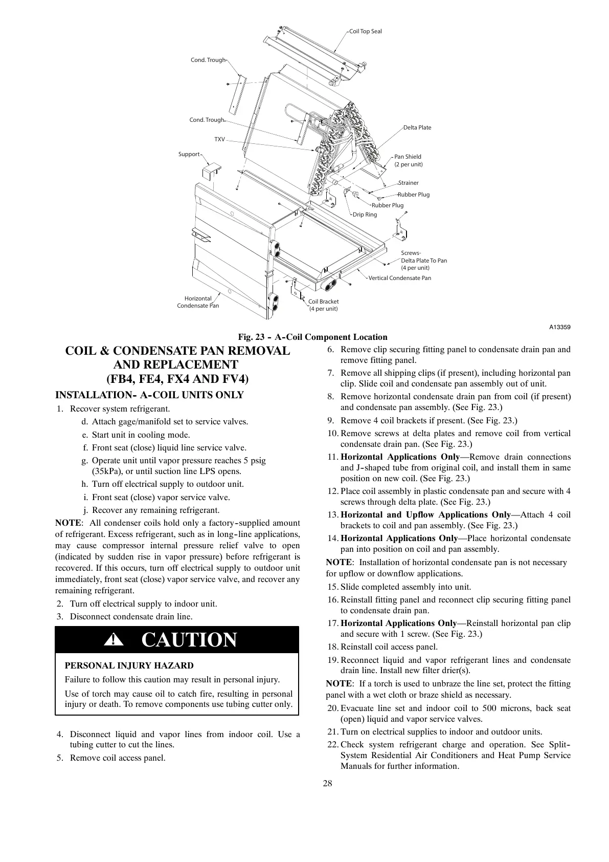
Fig. 23 -- A--Coil Component Location
COIL & CONDENSATE PAN REMOVAL
AND REPLACEMENT
(FB4, FE4, FX4 AND FV4)
INSTALLATION-- A--COIL UNITS ONLY
1. Recover system refrigerant.
d. Attach gage/manifold set to service valves.
e. Start unit in cooling mode.
f. Front seat (close) liquid line service valve.
g. Operate unit until vapor pressure reaches 5 psig
(35kPa), or until suction line LPS opens.
h. Turn off electrical supply to outdoor unit.
i. Front seat (close) vapor service valve.
j. Recover any remaining refrigerant.
NOTE: All condenser coils hold only a factory--supplied amount
of refrigerant. Excess refrigerant, such as in long--line applications,
may cause compressor internal pressure relief valve to open
(indicated by sudden rise in vapor pressure) before refrigerant is
recovered. If this occurs, turn off electrical supply to outdoor unit
immediately, front seat (close) vapor service valve, and recover any
remaining refrigerant.
2. Turn off electrical supply to indoor unit.
3. Disconnect condensate drain line.
PERSONAL INJURY HAZARD
Failure to follow this caution may result in personal injury.
Use of torch may cause oil to catch fire, resulting in personal
injury or death. To remove components use tubing cutter only.
CAUTION
!
4. Disconnect liquid and vapor lines from indoor coil. Use a
tubing cutter to cut the lines.
5. Remove coil access panel.
6. Remove clip securing fitting panel to condensate drain pan and
remove fitting panel.
7. Remove all shipping clips (if present), including horizontal pan
clip. Slide coil and condensate pan assembly out of unit.
8. Remove horizontal condensate drain pan from coil (if present)
and condensate pan assembly. (See Fig. 23.)
9. Remove 4 coil brackets if present. (See Fig. 23.)
10. Remove screws at delta plates and remove coil from vertical
condensate drain pan. (See Fig. 23.)
11. Horizontal Applications Only—Remove drain connections
and J--shaped tube from original coil, and install them in same
position on new coil. (See Fig. 23.)
12. Place coil assembly in plastic condensate pan and secure with 4
screws through delta plate. (See Fig. 23.)
13. Horizontal and Upflow Applications Only—Attach4coil
brackets to coil and pan assembly. (See Fig. 23.)
14. Horizontal Applications Only—Place horizontal condensate
pan into position on coil and pan assembly.
NOTE: Installation of horizontal condensate pan is not necessary
for upflow or downflow applications.
15. Slide completed assembly into unit.
16. Reinstall fitting panel and reconnect clip securing fitting panel
to condensate drain pan.
17. Horizontal Applications Only—Reinstall horizontal pan clip
and secure with 1 screw. (See Fig. 23.)
18. Reinstall coil access panel.
19. Reconnect liquid and vapor refrigerant lines and condensate
drain line. Install new filter drier(s).
NOTE: If a torch is used to unbraze the line set, protect the fitting
panel with a wet cloth or braze shield as necessary.
20. Evacuate line set and indoor coil to 500 microns, back seat
(open) liquid and vapor service valves.
21. Turn on electrical supplies to indoor and outdoor units.
22. Check system refrigerant charge and operation. See Split--
System Residential Air Conditioners and Heat Pump Service
Manuals for further information.