29
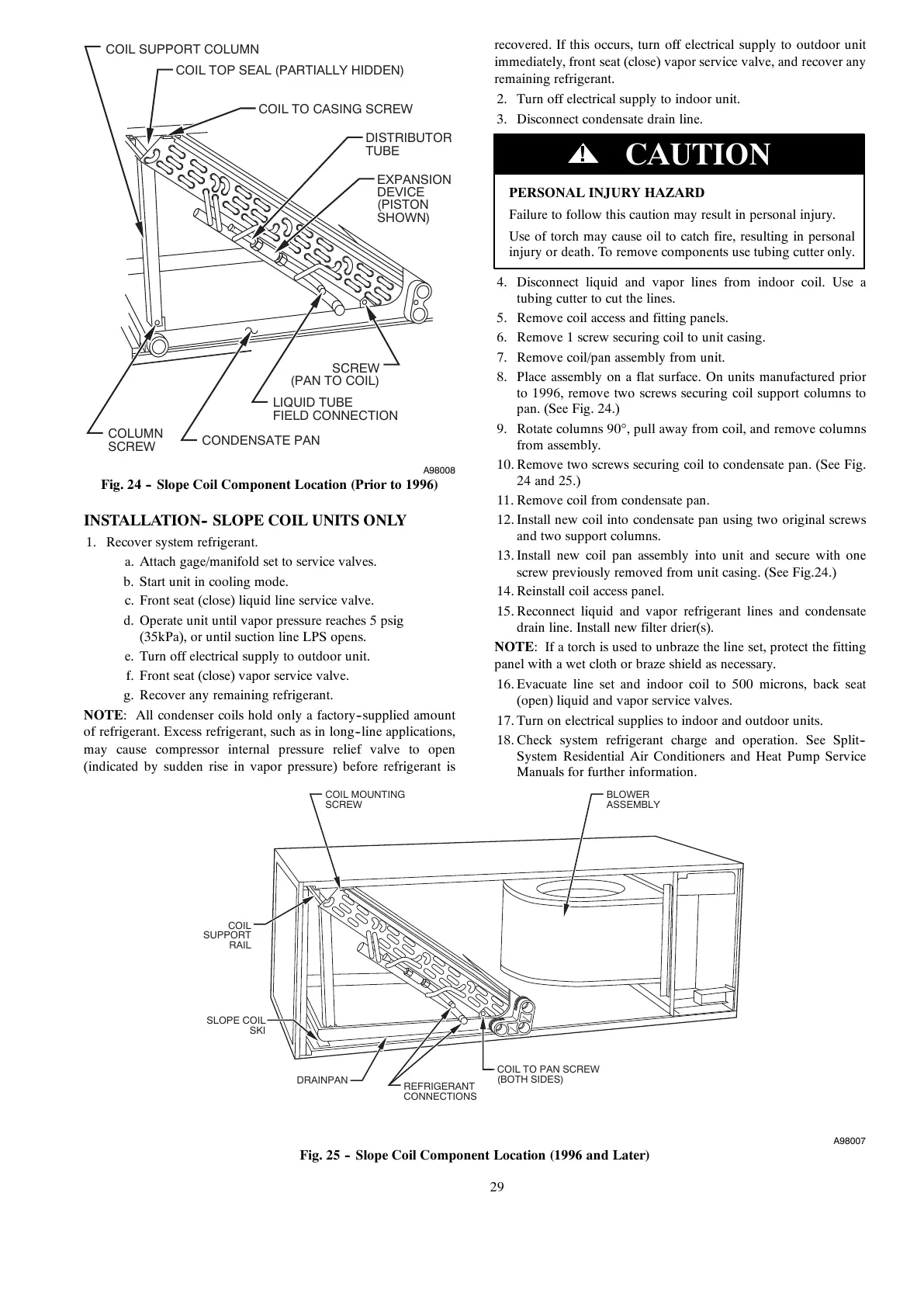
CONDENSATE PAN
EXPANSION
DEVICE
(PISTON
SHOWN)
DISTRIBUTOR
TUBE
COIL TO CASING SCREW
COIL TOP SEAL (PARTIALLY HIDDEN)
SCREW
(PAN TO COIL)
LIQUID TUBE
FIELD CONNECTION
COLUMN
SCREW
COIL SUPPORT COLUMN
A98008
Fig. 24 -- Slope Coil Component Location (Prior to 1996)
INSTALLATION-- SLOPE COIL UNITS ONLY
1. Recover system refrigerant.
a. Attach gage/manifold set to service valves.
b. Start unit in cooling mode.
c. Front seat (close) liquid line service valve.
d. Operate unit until vapor pressure reaches 5 psig
(35kPa), or until suction line LPS opens.
e. Turn off electrical supply to outdoor unit.
f. Front seat (close) vapor service valve.
g. Recover any remaining refrigerant.
NOTE: All condenser coils hold only a factory--supplied amount
of refrigerant. Excess refrigerant, such as in long--line applications,
may cause compressor internal pressure relief valve to open
(indicated by sudden rise in vapor pressure) before refrigerant is
recovered. If this occurs, turn off electrical supply to outdoor unit
immediately, front seat (close) vapor service valve, and recover any
remaining refrigerant.
2. Turn off electrical supply to indoor unit.
3. Disconnect condensate drain line.
PERSONAL INJURY HAZARD
Failure to follow this caution may result in personal injury.
Use of torch may cause oil to catch fire, resulting in personal
injury or death. To remove components use tubing cutter only.
CAUTION
!
4. Disconnect liquid and vapor lines from indoor coil. Use a
tubing cutter to cut the lines.
5. Remove coil access and fitting panels.
6. Remove 1 screw securing coil to unit casing.
7. Remove coil/pan assembly from unit.
8. Place assembly on a flat surface. On units manufactured prior
to 1996, remove two screws securing coil support columns to
pan. (See Fig. 24.)
9. Rotate columns 90°, pull away from coil, and remove columns
from assembly.
10. Remove two screws securing coil to condensate pan. (See Fig.
24 and 25.)
11. Remove coil from condensate pan.
12. Install new coil into condensate pan using two original screws
and two support columns.
13. Install new coil pan assembly into unit and secure with one
screw previously removed from unit casing. (See Fig.24.)
14. Reinstall coil access panel.
15. Reconnect liquid and vapor refrigerant lines and condensate
drain line. Install new filter drier(s).
NOTE: If a torch is used to unbraze the line set, protect the fitting
panel with a wet cloth or braze shield as necessary.
16. Evacuate line set and indoor coil to 500 microns, back seat
(open) liquid and vapor service valves.
17. Turn on electrical supplies to indoor and outdoor units.
18. Check system refrigerant charge and operation. See Split--
System Residential Air Conditioners and Heat Pump Service
Manuals for further information.
COIL MOUNTING
SCREW
BLOWER
ASSEMBLY
COIL
SUPPORT
RAIL
SLOPE COIL
SKI
REFRIGERANT
CONNECTIONS
COIL TO PAN SCREW
(BOTH SIDES)
DRAINPAN
A98007
Fig. 25 -- Slope Coil Component Location (1996 and Later)