FB, FE, FF1E, FFM, FG, FH, FJ, FMA, FT, FV, FX, FY, FZ, F54, PF: Service and Maintenance Instructions
Manufacturer reserves the right to change, at any time, specifications and designs without notice and without obligations.
15
outdoor unit and the R, C, Y, O, W outdoor unit terminal strip
connections and will display Status Code 16, System Communication
Fault, on amber STATUS LED. No further fan coil troubleshooting
information will be available at User Interface until communications are
re-established.
If COMM LED does not light within proper time period and status code
is not displayed:
1. Check system transformer high and low voltage to be sure the
system is powered.
2. Check fuse on fan coil control to be sure it is not blown. If fuse is
open, check system wiring before replacing it to be sure a short
does not cause a failure of replacement fuse.
If COMM LED does not light within proper time period and status code
is displayed:
Check system wiring to be sure User Interface is powered and
connections are made A to A, B to B, etc. and wiring is not shorted.
Mis-wiring or shorting of the ABCD communications wiring will not
allow successful communications.
NOTE: Shorting or mis-wiring low voltage system wiring will not cause
damage to fan coil control or User Interface but may cause low voltage
fuse to open.
ECM Motor Troubleshooting
The ECM motor used in this product consists of two parts: the control
module and the motor winding section. Do not assume motor or module
is defective if it will not start. Use the designed-in LED information aids
and follow troubleshooting steps described below before replacing
motor control module or entire motor. Motor control module is available
as a replacement part.
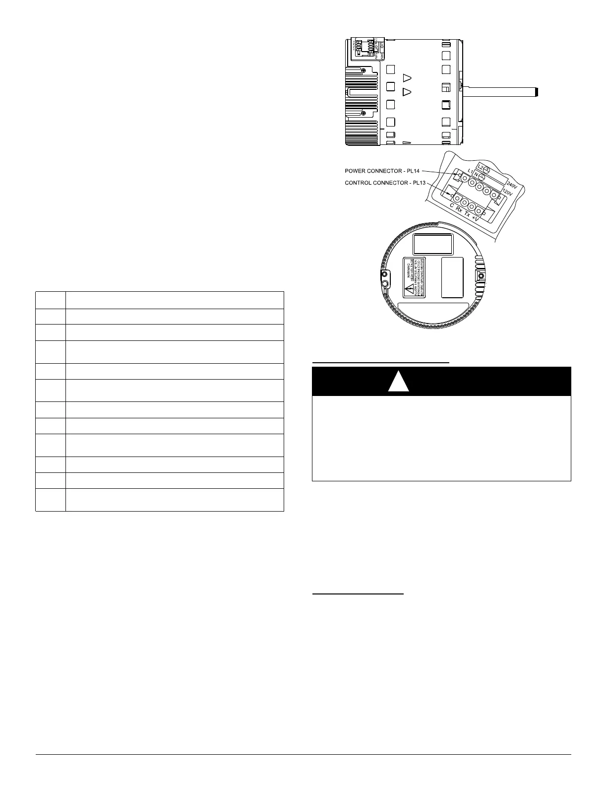
A12231
Fig. 13 – FE4/FE5 ECM Motor
Vefify Motor Winding Section
Before proceeding to replace a motor control module:
1. Check motor winding section to be sure it is functional.
2. Remove motor control module section and unplug winding plug.
Motor shaft should turn freely, resistance between any two motor
leads should be similar and resistance between any motor lead and
unpainted motor end should exceed 100,000 ohms.
3. Failing any of these tests, entire ECM motor must be replaced.
4. Passing all of the tests, motor control module alone can be replaced.
Motor Turns Slowly
1. Low static pressure loading of blower while access panel is
removed will cause blower to run slowly. Particularly at low
airflow requests. This is normal, do not assume a fault exists.
2. Recheck airflow and system static pressure using User Interface
service screens with access panel in place.
NOTE: Blower motor faults will not cause a lockout of blower
operation. Fan coil control will attempt to run the blower motor as long
as User Interface maintains a demand for airflow. Fan coil control will
not operate electric heaters while a fault condition exists. The fan coil
control communicates with the motor at least once every five seconds,
even when the motor is idle. If, during operation, the fan coil control
does not communicate with the motor for more than 25 seconds, the
motor will shut itself down and wait for communications to be reestablished.
Table 9 – Troubleshooting Status Codes
Code Description / Procedure Link to Text
16
(STATUS CODE 16, SYSTEM COMMUNICATION FAULT: on p17)
45
(STATUS CODE 45, CONTROL BOARD TEST FAULT: on p16)
37
(STATUS CODE 37, HEATER OUTPUT SENSED “ON” WHEN NOT
ENERGIZED: on p16)
44
(STATUS CODE 44, MOTOR COMMUNICATION FAULT: on p16)
25
(STATUS CODE 25, INVALID MOTOR / MODEL SELECTION:
on p16)
27
(STATUS CODE 27, INVALID OUTDOOR UNIT SIZE: on p16)
26
(STATUS CODE 26, INVALID HEATER SIZE: on p16)
36
(STATUS CODE 36, HEATER OUTPUT NOT SENSED WHEN
ENERGIZED: on p17)
41
(STATUS CODE 41, BLOWER MOTOR FAULT: on p17)
46
(STATUS CODE 46, BROWNOUT CONDITION: on p17)
53
(STATUS CODE 53, OUTDOOR AIR TEMPERATURE SENSOR
FAULT: on p17)
WARNING
!
ELECTRICAL SHOCK HAZARD
Failure to follow this warning could result in personal injury or death or
possible equipment damage.
After disconnecting power from the ECM motor, wait at least five
minutes before removing the control section. Internal capacitors require
time to discharge. Minor injury from electrical shock may result from
early contact with live metal parts.