FB, FE, FF1E, FFM, FG, FH, FJ, FMA, FT, FV, FX, FY, FZ, F54, PF: Service and Maintenance Instructions
Manufacturer reserves the right to change, at any time, specifications and designs without notice and without obligations.
29
2. The suction pressure at the outlet of the evaporator coil is
transferred via the external equalizer tube to the underside of the
diaphragm.
The bi-flow TXV is used on split system heat pumps. In cooling mode,
the TXV operates the same as a standard TXV previously explained.
However, when the system is switched to heating mode of operation,
refrigerant flow is reversed.
The bi-flow TXV has an additional internal check valve and tubing.
These additions allow refrigerant to bypass TXV when refrigerant flow
is reversed with only a 1-psig to 2-psig pressure drop through device.
When heat pump switches to defrost mode, refrigerant flows through a
completely open (not throttled) TXV. The bulb senses the residual heat
of outlet tube of coil that had been operating in heating mode (about
85° F and 155 psig). This temporary, not-throttled valve decreases
indoor pressure drop, which in turn increases refrigerant flow rate,
decreases overall defrost time, and enhances defrost efficiency.
Problems Affecting TXV
Low Suction Pressure
1. Restriction in TXV
2. Low refrigerant charge
3. Low indoor load
4. Low evaporator airflow
High Suction Pressure
1. Overcharging
2. Sensing bulb not secure to vapor tube
3. High indoor load
4. Large evaporator face area
NOTE: When installing or removing TXV, wrap TXV with a wet cloth.
When reattaching TXV, make sure sensing bulb is in good thermal
contact with suction tube.
5. The needle valve on pin carrier is spring-loaded, which also exerts
pressure on underside of diaphragm via push rods, which closes
valve. Therefore, bulb pressure equals evaporator pressure at outlet
of coil plus spring pressure. If load increases, temperature increases
at bulb, which increases pressure on topside of diaphragm, which
pushes pin carrier away from seal, opening valve and increasing
flow of refrigerant. The increased refrigerant flow causes increased
leaving evaporator pressure which is transferred via the equalizer
tube to underside of diaphragm, with which the pin carrier spring
pressure closes valve. The refrigerant flow is effectively stabilized
to load demand with negligible change in superheat.
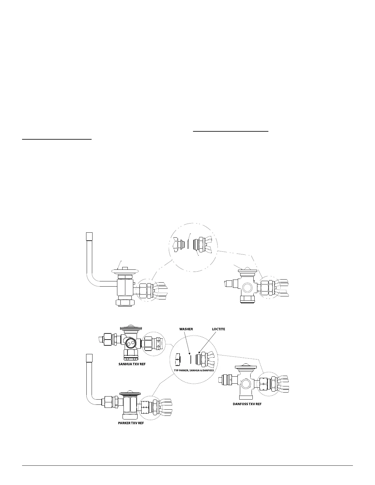
Aluminum Coil Unit TXV’s
The distributor used on the all-aluminum coils is also made of
aluminum. The TXV connection to the distributor is accomplished with
a 3/4" Chatleff nut (Fig. 26). The threads are coated with Loctite Heavy
Duty Anti-Seize which is a graphite/calcium fluoride formulation, for
applications that is free from copper, lead and sulfur. This product is
typically used in applications with an operating range of -20° F to
+2400° F. When replacing a TXV it is recommended to reapply with the
same thread sealer.
Extra care should be taken during brazing of copper equalizer on the
aluminum coils to prevent the braze material from splattering on the
aluminum. Also, route the copper equalizer so that it doesn’t touch the
aluminum components.
A14212
Fig. 26 – Aluminum Coil Unit TXV’s
A230413
Fig. 27 – TXV Examples (Mechanical)
Loctite
Washer
Thermal
Expansion Valve
Thermal
Expansion Valve