© 2024 Carrier. All rights reserved.
A Carrier Company
Edition Date: 7/24
Catalog No: SM-FANCOIL-10
Replaces: SM-FANCOIL-09
FB, FE, FF1E, FFM, FG, FH, FJ, FMA, FT, FV, FX, FY, FZ, F54, PF: Service and Maintenance Instructions
Manufacturer reserves the right to change, at any time, specifications and designs without notice and without obligations.
33
13. 1Remove screw at bottom of coil extension and reuse to attached
Coil Baffle in same location. Long side of baffle toward pan
(Fig. 32 and Fig. 33).
14. Install new coil into condensate pan using two original screws and
two support columns.
15. Install new coil pan assembly into unit and secure with one screw
previously removed from unit casing (Fig. 32).
16. Reinstall coil access panel.
17. Reconnect liquid and vapor refrigerant lines and condensate drain
line. Install new filter drier(s).
NOTE: If a torch is used to unbraze the line set, protect the fitting panel
with a wet cloth or braze shield as necessary.
18. Evacuate line set and indoor coil to 500 microns, back seat (open)
liquid and vapor service valves.
19. Turn on electrical supplies to indoor and outdoor units.
20. Check system refrigerant charge and operation. See Split- System
Residential Air Conditioners and Heat Pump Service Manuals for
further information.
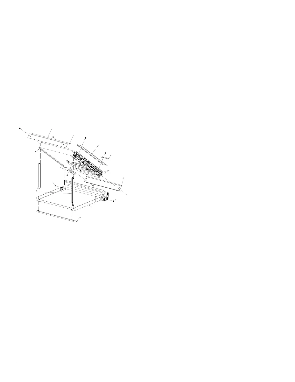
A14307
Fig. 33 – Slope Coil Component Location (1996 and Later)
Coil Bracket
Coil Extension
Coil Baffle
Condensate Pan
Shield
Condensate Pan
Assembly
Slope Coil Ski
Splash Guard
Coil and Header
Assembly
Coil Supports
Coil-to-Pan
Screw
Coil-to-Pan
Screw
Coil Mounting Screw
Location
Refrigerant
Connections