Do you have a question about the Carrier Viento 200 and is the answer not in the manual?
Provides rules for correctly installing VIENTO 200/300/350 units.
Mandatory safety precautions before electrical operation and personal protective equipment.
Recommendations for drain hose angle and descent for proper water drainage.
Instructions for unpacking the unit and verifying contents against the bill of material.
Guidance on vehicle partition installation and air intake considerations.
Protect the vehicle roof and box floor before preparation and unit installation.
Details the three possibilities to fit the unit: Roof top, Nosemount, and Roof cut mounting.
Instructions for drilling fixing holes and a larger hole for harnesses and hoses.
Steps for installing silent blocks and waterproofing the mounting points.
Drilling holes for passing harnesses and hoses between condenser and evaporator.
Instructions for drilling fixing and harness/hoses holes for nosemount installation.
Marking and drilling fixing holes for the evaporator with space considerations.
Installing inserts using an adapted tool for reinforced body installations.
Drilling the electrical harness and hoses hole inside the box.
Drilling the drain water hose hole inside the body with a recommended descent.
Drilling and countersinking holes for mushroom fasteners on the roof.
Measuring roof thickness and adjusting mushroom length for proper fitting.
Applying silicone and installing mushrooms with a mallet for a secure fit.
Steps to remove the unit's grill by unscrewing fixing screws.
Procedure for removing the top cover by unscrewing rear fixing screws.
Instructions for roof/cut mounting, nosemount, and placing the unit on silent blocks.
Removing side panels, mounting evaporator, checking distance, and tightening screws.
Guidelines for stocking refrigeration hoses: clean, dry, sheltered, and with capped ends.
Tips for right hose installation: no twists, adequate length, using elbows, and respecting curve radius.
Tools required and steps for cutting hoses, adding oil, and using double-clic clamps.
Lubricating fittings, removing caps, inserting connectors, and crimping clamps.
Instructions for running electrical harnesses and ignition cable inside the vehicle body.
Running refrigeration and drain water hoses inside the vehicle body with marking recommendations.
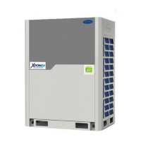
Identification of the four hoses to be connected: oil return, high pressure, liquid, and hot gas lines.
Connecting the oil return and high pressure lines to the oil separator and compressor.
Connecting hot gas and liquid lines to the valve, filter drier, and serpentin inlet.
Attaching all hoses and harnesses securely using plastic tie-wraps.
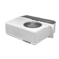
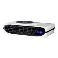
Details the three hoses connecting to the evaporator: suction, liquid, and hot gas lines.
Connecting suction, hot gas, and liquid lines to the evaporator fittings.
Installing the RAT sensor and connecting evaporator fan connectors.
Placing the drain water pipe, connecting hoses, and insulating evaporator sides.
Drilling the cab floor for hoses and cables, protecting the hole, and routing them.
Routing the cab command harness to the vehicle dashboard and recommendations for protection.
Fitting the cab command in the specified location, with precautions for dashboard installation.
Moving and attaching the harness to the compressor and chassis using tie-wraps.
Connecting the high pressure, suction pressure, and oil return hoses to the compressor.
Installing the injection thermostat on the high pressure line fitting with a clamp.
Protecting thermostat wires with a sleeve and maintaining cables with tie-wraps.
Routing ignition cable, connecting white wire, and installing the 1A fuse.
Insulating connectors, stripping and crimping battery ground, and installing fuse holders.
Installing the 80 amp fuse, protection cap, and connecting unit/battery ground.
Steps for performing a gas leak check using vacuum pump, nitrogen, and bubble water.
Procedure for evacuating the circuit, including triple evacuation and vacuum check.
Requirements for charging: manifold gauges, refrigerant cylinder, scale, and charging process.
Specifies refrigerant charge amounts for Viento 200, 300, and 350 models.
Explanation of the Compressor Regulation valve and its importance for unit capacity and operation.
Steps for connecting manifold, adjusting CPR using wrenches, and tightening jam nut.
Explanation of the Thermo Expansion valve's function in metering refrigerant and controlling superheat.
Steps for connecting manifold, running unit in cooling mode, and adjusting superheat.
| Brand | Carrier |
|---|---|
| Model | Viento 200 |
| Category | Air Conditioner |
| Language | English |