GB - 17
Zone Manager
ENGLISH
Diagnostic erros
Displayed error "A2" Temperature sensor error!
Check temperature sensor for damage.
If recycling power does not clear display, replace the Zone Manager.
Displayed error "Cx" Communication error with unit(s) in zone (x)!
Where x is a number identifying a zone. 1) Put the zone manager into "Installation Test" mode and check unit(s) LED to blink rapidly.
If the units LED does not blink:
1) Configure unit for the proper zone and re-try "COMM" mode.
2) Check communication wiring
3) Check prime board installation.
Displayed error "Fx" Unit(s) in zone (x) has recorded a failure! 1) go to the unit(s) in zone (x) and determine the cause
Where x is a number identifying a zone. of the failure.
System errors
System does not Heat/Cool 1) If diagnostic code is displayed, check diagnostic trouble shooting table.
2) Put the zone manager into "Installation Test" mode and check unit’s LED to blink rapidly.
If the unit’s LED does not blink:
1) Configure unit for the proper zone and re-try "Installation Test".
2) Check communication wiring.
3) Check prime board installation.
3) Select Heat/Cool mode. Adjust the set point so that there is a real heating or cooling request.
Wait for unit’s time guard to expire. If unit does not operate, check unit for errors.
If unit does operate, Check the Zone Managers programming for scheduling errors.
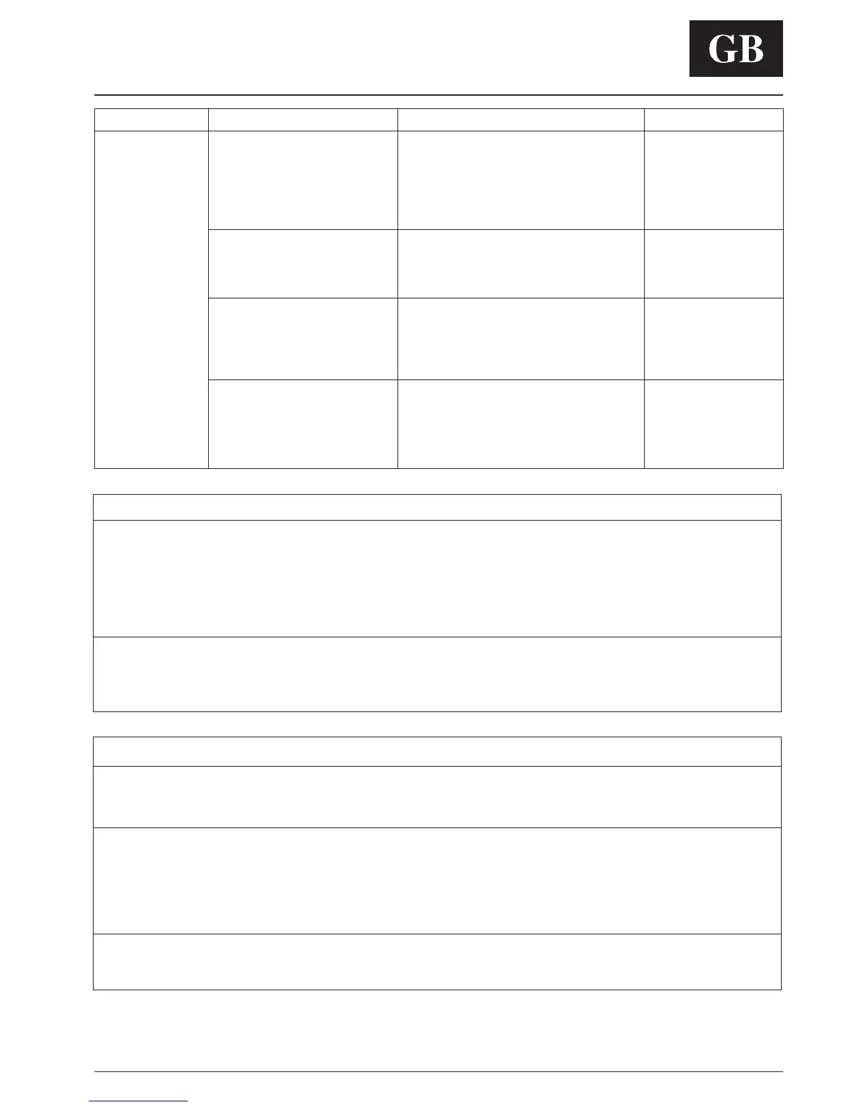
Symptom Possible Cause Things to check Solution
No LCD display 1) mis-wiring of the 12 volt
power to Zone Manager control.
2) Power not online
3) No 12 volts on +12
and GND of terminal block.. .
1) Make sure the cable
connections are correct
2) The Zone Manager control
is damaged.
+12 volts applied to
CZM at the correct
terminals and still
does not operate
1) Verify that +12 v and Gnd are connected to the
proper terrminals of the Zone Manager control and
the COM board. Reference Installlation wiring section
for correct connections
2) Check pin connections of Zone Manager to base
plate terminal block while closing the plastic.
1) Check that the units main power is connected. The
main control board should be operating normally
1) Check the installation of the COM board. Check to
see that the 9 pin connection of the COM board to
main board is correct.
After disconnecting the power,
correct the wiring problem and
re-cycle power.
After verifing the wiring to the
Zone Manager control, re-cycle
the unit power.
After disconnecting the power,
correct the wiring problem and
re-cycle power.
Verify wiring did not damage
the Zone Manager.
Change the Zone Manager
control and re-cycle power.
Trouble Shooting

 Loading...


