GB - 5
Zone Manager
ENGLISH
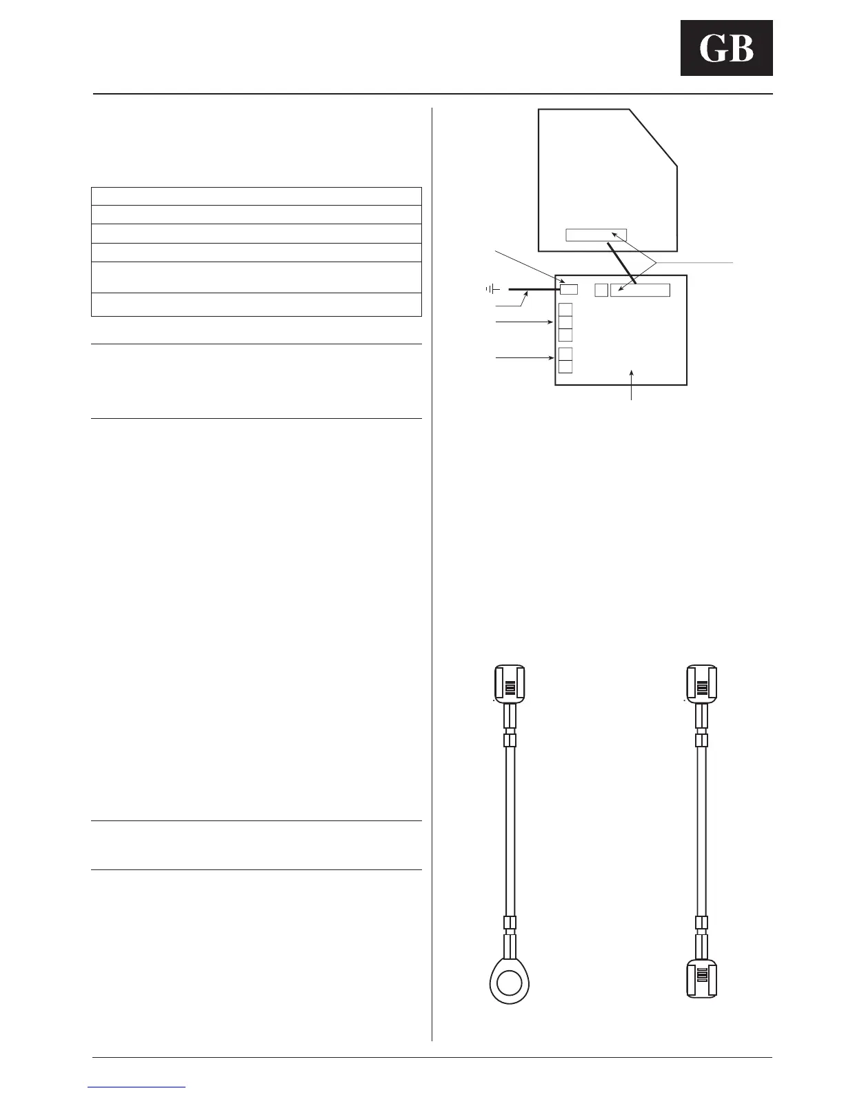
1 Board to board connector
2 Internec communication board (COM)
3 P1 earth connector
4 RS 485 communications
5 ZM power supply only required for the unit closes to the ZM
6 Cable connecting board to ground post
HWX - HWS - GKX VKX
1
2
3
6
4
5
J3 J1
J2
P1
Electrical connections
Installation of the kit into the unit
Skip this paragraph if the unit does not need the installation of
a kit.
Kit part number Unit type
40 GKX 40QKX900---102-40
40 QKX None
42 HWX and 42 HWS 40QKX900---102-40
42 HWX with
None
electric heater
42 VKX 40QKX900---102-40
CAUTION:
Improper wiring or installation may damage the Zone
Manager.
Check to make sure wiring is correct before proceeding
with turning on unit.
A communication board is required for all products that are
networked to a Zone Manager system.
Reference the table on products that the Zone Manager can
be networked with, it identifies whether an installation kit is
required or not.
If required:
• A kit consists of a communication board, a 9 pin wire harness
and a ground wire and a jumper.
• The Jumper has to be installed to connector J3 in the
Internec communication board (only for models 42HWX,
42HWS and 42VKX).
• The 9 pin wire harness must be attached to connector J1 on
the communication board and routed to the J2 EXPANSION
connector on the main control board.
The main control board will have to be removed to make this
connection.
Once the wire harness is attached to the main control board,
it should be inserted back into the control box (only for
models 42HWX, 42HWS and 42VKX)
• The ground wire must be attached from the ground post on
the unit, to the 4.8 mm quick connect (P1) on the
communication board.
ATTENTION:
Two ground wires are available: use the right one for the
corresponding unit.
• Now, the network communication wires need to be installed
into the 3 poles terminal block on the communication board.
• Finally, if this unit will power the Zone Manager, 12V power
wires need to be installed into the 2 position terminal block on
the communication board.
• Once all the wiring is complete, the communications board
can be inserted into the control box.

 Loading...


