GB - 6
Zone Manager
Electrical connections
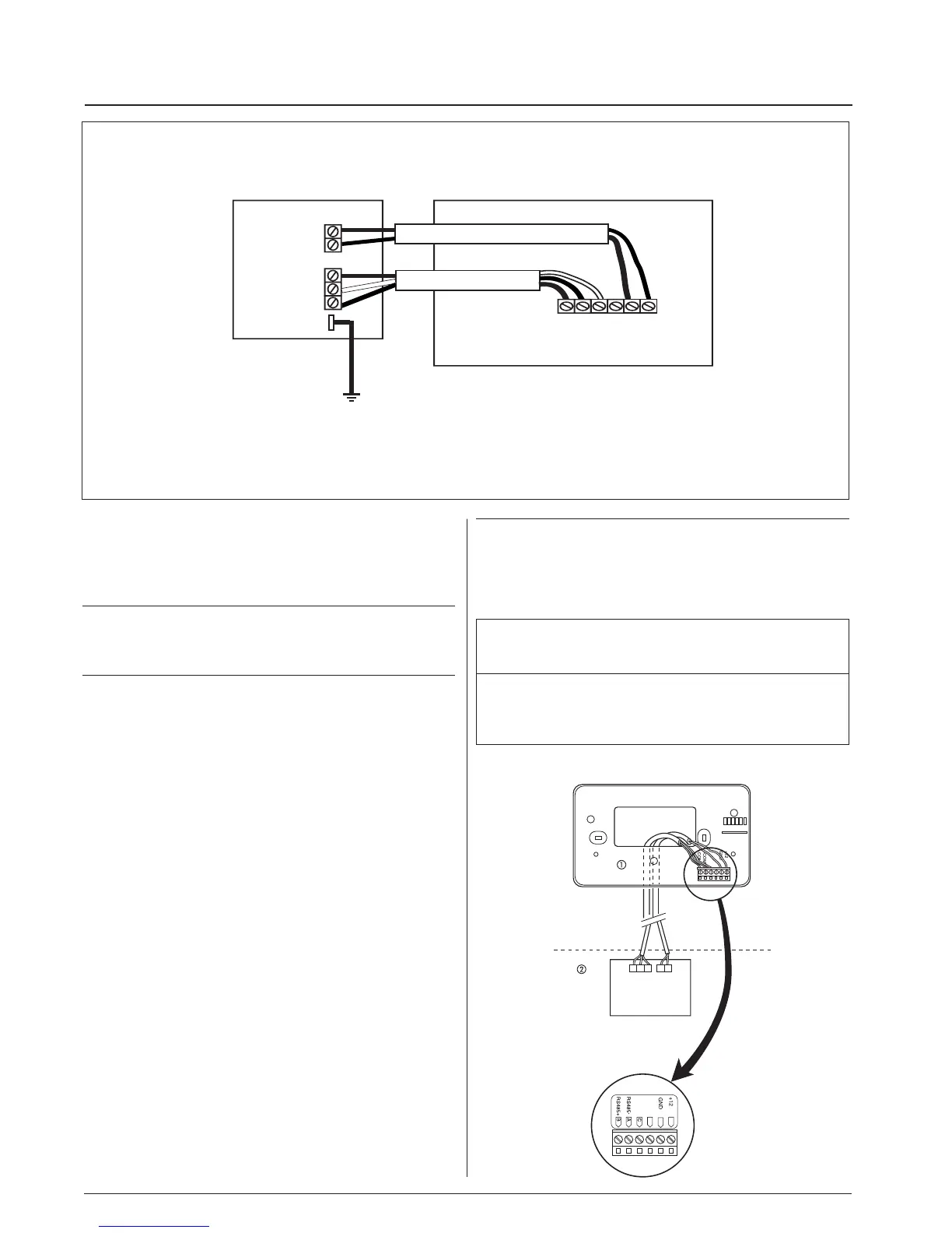
Diagram 1: wiring for Zone manager
Communication Board
Zone Manager
To the unit
Ground post
BAC
Gnd 12 V
GND
+12
BK
WH
RD
P1
BK
RD
BK
RD
Wiring Zone Manager to master unit
The Zone Manager has the ability to control up to 32 units.
To insure the correct operation of this system the wiring must
be installed using the following guidelines.
WARNING:
Before connecting any wiring to the Zone Manager , turn off all
power to the unit that will supply power to the Zone Manager.
Electrical shock can cause personal injury or death.
The Zone Manager is connected to the master unit using the
following instructions. Reference Diagram 1 when making these
connections.
POWER CABLE CONNECTIONS
(2 conductor, double insulated cable)
• In the Zone Manager, loosen the screws on the terminals
labled +12V and GND.
• Insert the RED wire into the terminal labled +12V. Tighten the screw.
• Insert the BLACK wire into the terminal labled GND.
Tighten the screw.
• At the communications board in the master unit product,
loosen the screws on the terminals labled +12V and GND.
• Insert the RED wire into the terminal labled +12V.
Tighten the screw.
• Insert the BLACK wire into the terminal labled GND.
Tighten the screw.
• Power cable installation complete.
COMMUNICATION CABLE CONNECTIONS
(3 conductor, double insulated, shielded cable)
• In the Zone Manager, loosen the screws on the terminals
labled A, B, and C.
• Insert the RED wire into the terminal labled A. Tighten the screw.
• Insert the BLACK wire into the terminal labled B. Tighten the screw.
• Insert the WHITE wire into the terminal labled C. Tighten the screw.
• At the communications board in the master unit product,
loosen the screws on the terminals labled A, B, and C.
• Insert the RED wire into the terminal labled A. Tighten the screw.
• Insert the BLACK wire into the terminal labled B. Tighten the screw.
• Insert the WHITE wire into the terminal labled C. Tighten the screw.
• Connect the shield of the cable to the master unit GND post.
Communication cable installation complete.
B
C
A
BK Black
RD Red
WH White
a Zone Manager
b Unit
NOTE:
The shield for the communications cable is not connected at
the Zone Manager.
Terminate the shield in such a manner that it will not short with
anything in the Zone Manager.
Wiring Materials required
(supplied by installer)
• 1 small screwdriver
• 3 x 0,5 and 2 x 0,5 mm
2
multiple cables, double insulated.
Suggested type: H03VV-F.

 Loading...


