GB - 7
ENGLISH
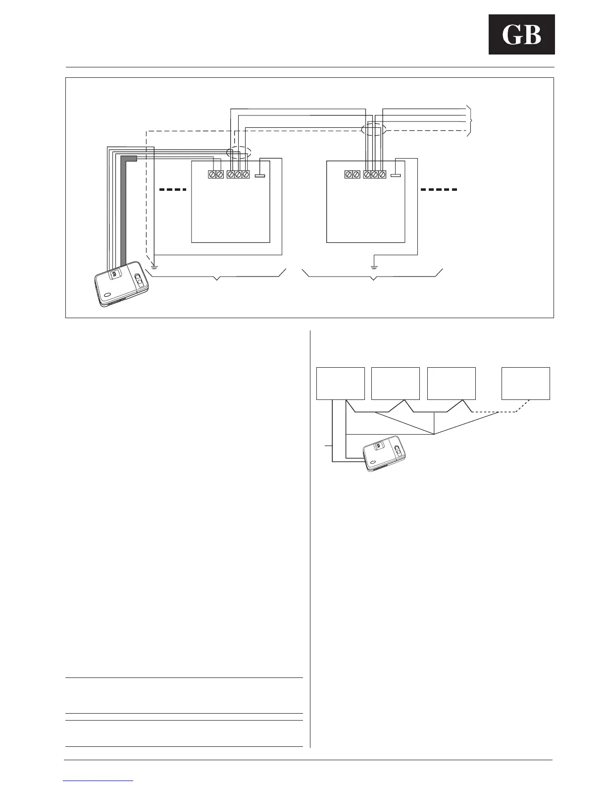
Zone Manager
Networking multiple units
Multiple units can be connected together and controlled by a
single Zone Manager.
Diagram 3 is a block diagram of multiple units networked into a
system controlled by 1 Zone Manager.
To accomplish this the communication boards from the networked
units must be wired together in a daisy chain configuration.
The following section describes how to do the wire installation
for a networked system.
Wiring for networking multiple units
Materials required for wiring multiple units into a network.
Reference Diagram 2 when doing this installation.
COMMUNICATION CABLE CONNECTIONS
(3 conductor, double insulated, shielded cable)
1. At the communications board in the master unit, loosen the
screws on the terminals labled A, B, and C.
2. Insert the RED wires from daisy chained communication
cables into the terminal labled A. Tighten the screw.
3. Insert the BLACK wire from daisy chained communication
cables into the terminal labled B. Tighten the screw.
4. Insert the WHITE wire from daisy chained communication
cables into the terminal
labled C. Tighten the screw.
5. Connect the SHIELD from the daisy chained cables
together.
Continues steps 1-4 until you reach the last unit in a network. At this
point only 1 wire needs to be inserted into each terminal.
Be sure in all cases when communications cables are daisy
chained, the shield wires are also daisy chained.
The shield wire must be grounded to the unit ground post in
one location on the system.
NOTE:
The shield for the communication cables is tied to a unit GND post at
one point only, the remaing shields are daisy chained together.
CAUTION:
Do not tie the shield to a GND post at more than 1 location.
Electrical connections
Zone Manager
Diagram 3: networking of multiple units
a
Diagram 2: multiple units in a network configuration
Zone Manager
1 Communications cables
2 To unit GND post
3 Connect to unit GND post
4 Connect to unit GND post
BK Black
RD Red
WH White
SH Shield
BK
RD
WH
BK
RD
WH
SH
ACBP1 P1
1
4
3
2
ACB
Unit 1
Unit 2
To other units
of the network
a Power connection
b Communication connections
b
UNIT 1 UNIT 2 UNIT 3 UNIT ....

 Loading...


