7. Fitting Fanmaster to the
installation box.
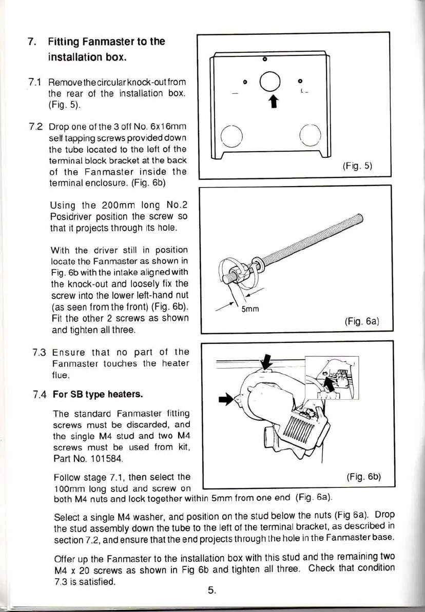
7.1 Remove thecircular knock-out from
the rear of the installation box.
(Fig.
5).
7.2 Drop one of the 3 off No. 6x16mm
self tapping screws provided down
the tube located to the left of the
terminal block bracket at the back
of the Fanmaster inside the
terminal enclosure. (Fig. 6b)
Using the 200mm long No.2
Posidriver position the screw so
that it projects through its hole.
With the driver still in position
locate the Fanmaster as shown in
Fig.
6b with the intake aligned with
the knock-out and loosely fix the
screw into the lower left-hand nut
(as seen from the front) (Fig. 6b).
Fit the other 2 screws as shown
and tighten all three.
7.3 Ensure that no part of the
Fanmaster touches the heater
flue.
7.4 For SB type heaters.
The standard Fanmaster fitting
screws must be discarded, and
the single M4 stud and two M4
screws must be used from kit,
Part No. 101584.
Follow stage 7.1, then select the
100mm long stud and screw on
o
C)
(Fig.
5)
5mm
(Fig.
6a)
(Fig.
6b)
both M4 nuts and lock together within 5mm from one end (Fig. 6a).
Select a single M4 washer, and position on the stud below the nuts (Fig 6a). Drop
the stud assembly down the tube to the left of the terminal bracket, as described in
section 7.2, and ensure that the end projects through the hole in the Fanmaster base.
Offer up the Fanmaster to the installation box with this stud and the remaining two
M4 x 20 screws as shown in Fig 6b and tighten all three. Check that condition
7.3 is satisfied.
5.
www.vwT4camper.info - a useful website for owners and enthusiasts of VW T4 Transporter Campervans


 To Next Page