12
Control Masters
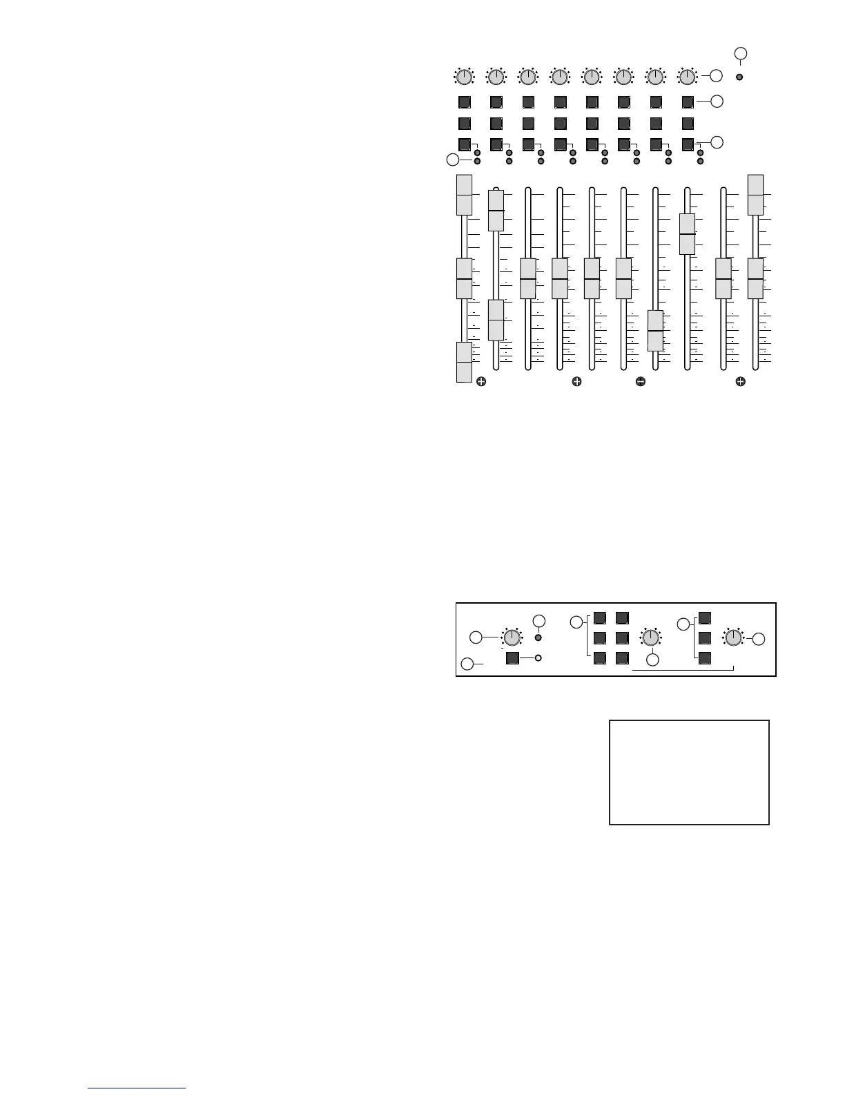
13. GROUP MUTE’S
The Group MUTE switch mutes the Group signal pre Fader and post insert.
This means the group output and L-R assignment are muted, but not the
send on the insert. The corresponding RED Mute LED indicates the Group
has been muted.
14. GROUP SOLO
The GROUP SOLO is an in place SOLO located after of the group PAN circuit.
15. GROUP L-R AND PAN
The Group L-R Assignment switch is located after the PAN circuit allowing
the group output to be assigned to either the left, the right, or any PAN set-
ting of both masters.
16. GROUP PEAK LED’S
The Group PEAK LED indicates the group is within 3db of clipping. The PEAK
LED is located pre fader post insert in order to indicate the peaking level of
the summing bus or insert return when the group insert is used.
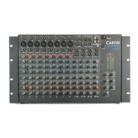
17. SOLO LEVEL
The SOLO level controls the volume of the SOLO bus heard through the control room (and channel PFL when used). The SOLO level also affects
the measured level seen on the L-R meters when something is soloed. This is why the SOLO is center detented to provide a unity gain location
for the solo circuit in order to indicate the desired soloed material correctly on the meters. For normal solos the meters indicate stereo in place
material, when using the channel PFL mode the meters indicate in mono the pre fader material on both meters.
18. SOLO LED
The SOLO led lights up when one or more solo switches have been pressed. The SOLO LED also indicates the control room and master L-R
meters are monitoring the pressed SOLO switches.
19. CHANNEL LISTEN MODE & PFL MODE INDICATOR
The channel listen mode switch provides the option of changing the channel SOLO switches from normally post PAN, stereo in-place solo switches
to pre fader PFL switches used in live applications. The PFL MODE led indicates the channels are in PFL mode.
20. CONTROL ROOM LEVEL
The CONTROL ROOM level adjusts the level of CONTROL ROOM outputs. This
is the master level when using the control room output for studio monitors
or when using the control room right output for PHONES.
21. CONTROL ROOM SELECTION SWITCHES
Use these switches to select what is heard through the control room outputs. When selected these switches
will be heard at the outputs. The switches perform as follows:
AUX 7-8: listens to the final output of the AUX 7-8 masters.
TAPE IN: listens to the post TAPE IN level input.
AUX 1-2: listens to the final output of the AUX 1-2 masters.
MONO: creates a control room left/right summed mono output on the control room outputs.
L-R: listens to the final output LEFT and RIGHT masters.
TO STUDIO: Inputs the control room output to the Studio output.
22. STUDIO LEVEL
The STUDIO level adjusts the level of STUDIO outputs. This is the master level when using the STUDIO outputs for a studio playback system or
when using the STUDIO right output for PHONES.
23. STUDIO SELECTION SWITCHES
Use these switches to select what is heard through the STUDIO outputs. When selected these switches will add together at the outputs.
The switches perform as follows: (Also see TO STUDIO above under the control room selection switches.)
AUX 7-8: listens to the final output of the AUX 7-8 masters.
AUX 1-2: listens to the final output of the AUX 1-2 masters.
L-R: listens to the final output LEFT and RIGHT masters.