The following section describes two of the more
common Studio recording setups. These setups
are not the only setups you can use, many of the
connections described here can be combined and
customized to provide the best setup for you.
The first Setup is based on the In-Line recording
method and the second setup is based on the Split
recording method.
In-Line Recording Setup.
The S/L series consoles are designed for In-line
recording. In-line recording is where each mixer channel can handle a mic input, a direct output to a multi-track and a tape return input from
the multi-track. This is due to the dual in-line channel format of the S/L series console. The dual In-line channel is made up of two individual
channel signal paths, a minor path for monitoring and a main, full featured path for tracking and final mix down. These two signal paths are
sourced by two inputs at the MIC input (including LINE IN) and the TAPE IN. With the use of the TAPE switch, either of the two input paths can
flow through either of the two signal paths.
When the TAPE switch is OUT, the MIC/LINE IN goes through the main signal path providing access to: the channel insert, the EQ section, all
the Auxiliaries, the Fader, the DIRECT OUTPUT and Bus assignments. The tape input goes through the minor path, which can be
accessed via the Aux 7-8 “TAPE” switch or the Aux 5-6 “TAPE 5-6” switch. This is the typical setup for tracking (recording instru-
ments to the multi-track unit’s
individual tracks), where a mic is
plugged into the channel’s XLR
MIC input. Then via the channel DIRECT
OUTPUT, the mic is recorded on one track of the
recording unit. At the same time on the chan-
nel, the output of the recording unit can be mon-
itored via the tape input and the Aux 7-8 TAPE
switch.
When the TAPE switch is IN the inputs are flipped
and the tape input goes through the main path
and the MIC goes through the
minor path. This is the typical
setup for mix down (where all the
recorded tracks are mixed to a
stereo mix). The MIC input can be used as an
input in the mix down to add more effects
returns and/or midi tracks to the stereo mix.
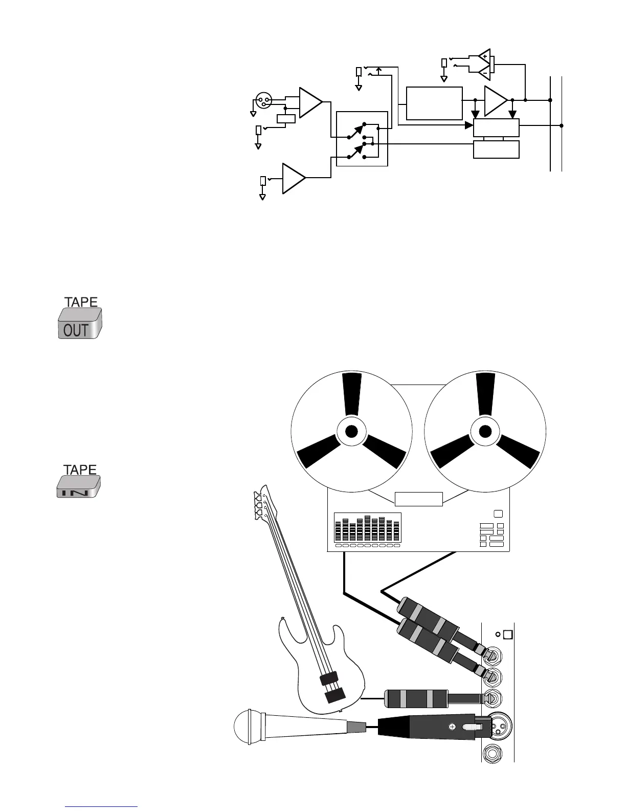
Figure 5-1 shows a block diagram of the chan-
nel and the modes of the TAPE switch. When
the TAPE switch is fully understood, it can
become a very powerful recording tool.
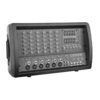
Figure 5-2 shows channel input connections for
the In-line format. Here the mic and line inputs
are both used in the example, but typically one
or the other would be used. In the example the
multi-track recorder is showing the inputs and
outputs of one track. The rest of the tracks would
be setup on the other channels in the same
manner. One of the key points here is that these
connections can be left connected in both the
tracking and mix down modes because the
TAPE switches re-patch the inputs for the two
modes internally.