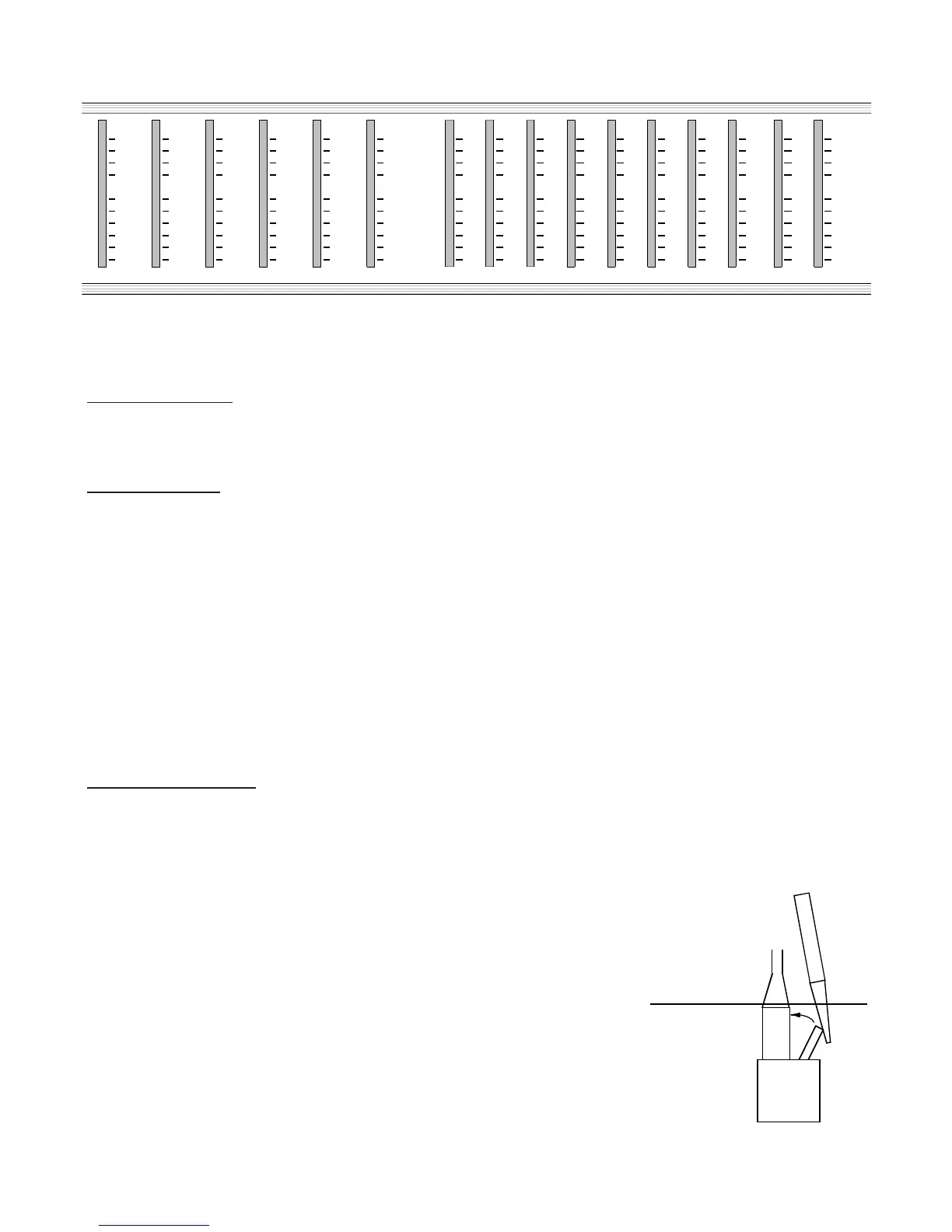
All three of the S/L series consoles feature a full 12-segment meter bridge.
Meter Operation
The S/L series meters are designed to indicate peak signal. This provides an indication of channel or master signal
levels to prevent channel or master overloading.
Meter Sources
Channels
The channel meters are sourced at the direct outputs. The direct output is after the fader and before the PAN cir-
cuitry. This location provides a continuous indication of the total channel operation. In live situations this indicates-
the levels going to the buses. In the studio this indicates the levels going to tape. In mixdown the meter indicates
the tape playback coming through the channel.
Masters
The master meters are for the Groups sourced at the XLR outputs. This is why the Group 1-4 meters will flip to the
AUX 1-4 sends when the AUX 1-4 FLIP switches are used. The left and right meters are actually sourced at the con-
trol room outputs pre the control room level control. The only thing that can be changed is when a SOLO has been
pressed. In this case the SOLO level can affect the level seen on the left and right meters. This can be corrected to
read true if the SOLO level control is set to the 0dB center detent position.
Meter Connections
The meters are connected to the console through the RJ45 plugs coming out of the back of the meter bridge.
Normally there is no reason these meter plugs should be removed. The power and left right plug is located above
the eight bus plug on the back of the meter. They plug into the mixer master section with the high plug on the meter
going into the farther plug on the master. Should the meter bridge not show any metering when powered up, check
these two plugs.
Removing the meter bridge
The meter bridge can be removed by first removing each of the meter RJ45 con-
nectors. These connectors have a key tab just below the mixer metal surface.
The tab is similar to a telephone connector tab and will need to be pressed flat
against the connector to release it from the mixer. The meter bridge is held on by
six screws on the back of the mixer at each end and two small screws on the
inside of the meter brackets that go into the top side of the mixer on each end.
The mixer will function normally with or without the meter bridge present.
8. Meter Bridge