4 - INSTRUMENTS/CONTROLS
75
Header Diagnostics
When a failure is detected, the header controller
indicator lamp in the instrumentation flashes on and
off and a Diagnostic Error Code is sent to the
instrumentation. An error message will be displayed
in place of the MPH or Rotor Speed. The letters “Hdr”
and a 2 or 3 digit code are alternately displayed.
The following table explains the failures that exist in
the Header Control System when the following codes
are displayed. They are listed from the highest
priority to the lowest priority. When more than one
failure exists simultaneously, only the highest priority
will be sent.
NOTE: If no engine speed is present, the feeder cannot be raised or lowered.
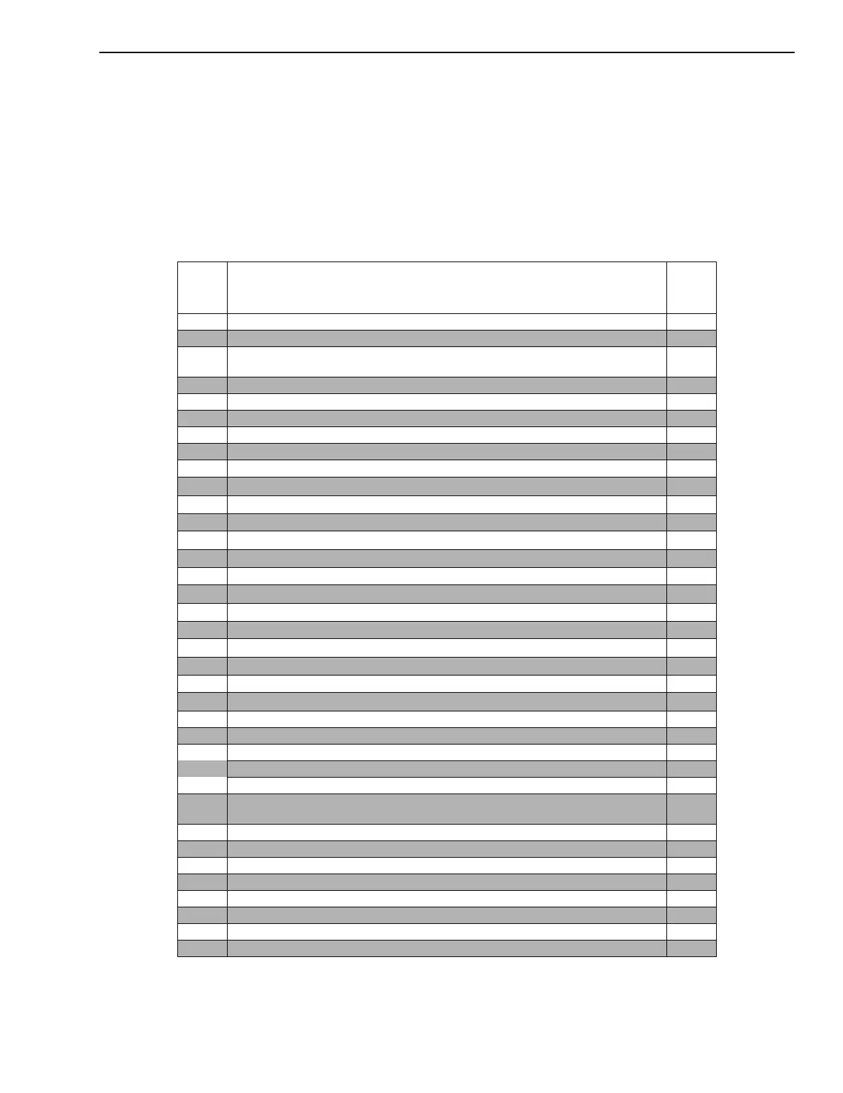
Inst.
Shown
Code Cause
Fail
Mode
HC0 Vehicle has never been calibrated. Halt
HC1 Calibration did not succeed or memory storage is bad. Halt
Hb0 All solenoid circuits open or short to ground or relay coil
circuit failure or relay contacts failed open.
Halt
Hu0 Open/short to ground - raise solenoid circuit failure. (1) Halt
Hu1 Short to 12v - raise solenoid circuit failure. Halt
Hu2 Short to 12v - raise solenoid driver. Halt
Hd0 Open/short to ground - lower solenoid circuit failure Halt
Hd1 Short to 12v - lower solenoid circuit failure. Halt
Hd2 Short to 12v - lower solenoid driver. Halt
Hr0 Open/short to ground - reel solenoid circuit failure. Halt
SCL No serial communications link from instrumentation. (2) Limp2
r1 Short to 12v - reel solenoid circuit failure. LImp2
r2 Short to 12v - reel drive driver. Limp2
E1 Loss of internal regulated voltage(s). Check height and float sensor wiring. Limp2
C2 Watchdog circuit failure. Limp2
E0 High battery supply voltage. Limp2
b1 Relay contacts failed closed. Limp2
S4 Open/Short - Air/Air Temperature circuit failure. Feeder disabled and buzzer on. (6 and 7) Limp2
P0 Open/short - Position Control circuit failure. Limp1
A0 Mode Select switch circuit failure. Limp1
S0 Feeder sensor circuit failure. Limp1
A1 Momentary Raise/Lower switch circuit failure D3
S1 Header Height sensor circuit failure (3 and 5) D2
S2 Float sensor circuit failure. D2
P1 Open/short - Sensitivity Control circuit failure.
For Float - Sensitivity will be 25% of pressure range. D1 (4)
For Header Height - Sensitivity will be 75%. D1 (4)
P2 Open/short - Reel/Ratio Speed Control circuit failure.
Reel/Ratio Speed will be 33% for reel speed and 1:1 for ratio speed.
D1 (4)
P3 Open/short - Lower Rate Control circuit failure. Lower Rate will be 10%. D1 (4)
P4 Open/short - Raise Rate Control circuit failure. Raise Rate will be 85%. D1 (4)
P5 Open/short - Min. Reel Speed Control circuit failure. Min. Reel Speed will be 9%. D1 (4)
S3 Concave Position Sensor circuit failure. D1
L1 Open/Short to ground - Air/Air lamp circuit failure. D1 (6)
L2 Short to 12v - Air/Air lamp circuit failure. D1 (6)
L3 Short to 12v - Air/Air lamp driver. D1 (6)
L0 Lamp circuit failure. D1
 Loading...