Issued 04-2010
1002-30
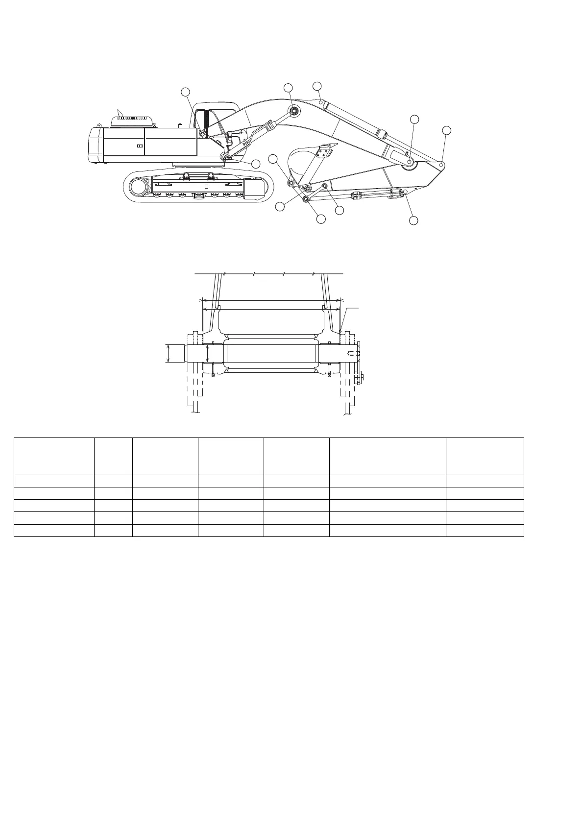
DIMENSIONS AND WEAR LIMITS OF ATTACHMENT MOBILE JOINTS
1. Boom foot/Frame
Part name Code
Measured
dimensions
(mm)
Standard
value (mm)
Usage limit
(mm)
Judgment Solution
Swing frame a 860 868 Acceptable/Unacceptable -
Boom b 857 855 Acceptable/Unacceptable Replacement
Clearance c 3.0 - 5.5 Adjust with shims Acceptable/Unacceptable Adjust with shims
Pin d Ø Ø110 Ø109 Acceptable/Unacceptable Replacement
Bushing (boom) e Ø Ø110 Ø111.5 Acceptable/Unacceptable Replacement
a
b
c
d
e
SI14004-001