V-R200 / VER.1
– 45 –
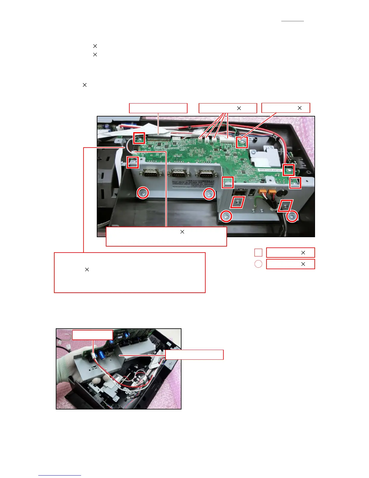
C-2. Remove the following parts.
(1) Connector 4 (Model with no Dallas key)
Connector 5 (Dallas key built in model)
(2) Printer FFC
(3) Tape, Ferrite core, Sub Display FFC
(4) Scrwe
12
NOTE: There are two types of screws (S2 × 8, S7 × 4).
(3) Tape, Ferrite core, Sub Display FFC
• Tape (15
50)
NOTE: Peel off the tape without giving a load to the FFC
and connector.
(1) Connector 4(2) Printer FFC
Screw (S2) 8
Screw (S7) 4
(1) Connector 1
V-R200-BD (Dallas key built in model) only
Ground wire 2
C-3. Remove the IOC ASSY.
C-4. Disconnect the connectors.
IOC ASSY
Connector