EasyManua.ls Logo

Cassese CS 940 - Left Arm Installation

Cassese CS 940
72 pages
Print Icon
To Next Page IconTo Next Page
To Previous Page IconTo Previous Page
Loading...
USER & PARTS MANUAL
CS940
20
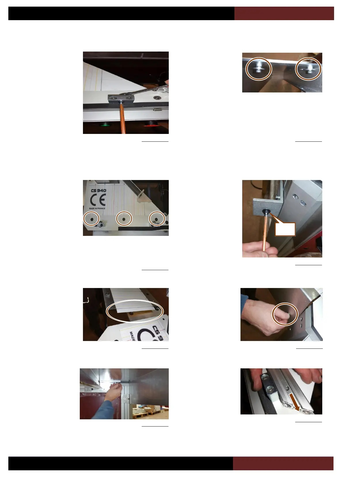
4.B.b Left arm installation
Unlock of 3 turns the 2
front horizontal
screws.
Figure 4-28
Remove the 2 screws
(V4) and (V5), discard
the nut which was just
installed to avoid
damaging in transport
the scale with a too
long screw.
Figure 4-29
Unlock the 3 screws
(ULF) on the top of the
table.
Figure 4-30
Remove the screw
(V6) in front of the
machine, keep that
screw, nut and washer
as they will have to be
installed in exact
same position.
Figure 4-31
Start to install the left
arm (7) taking care of
not damaging the
scale.
Figure 4-32
Figure 4-33
With the help of a
second person, install
back the screw (V6)
but do not block the
screw.
Figure 4-34
Still with the help of
the second person,
put back both screws
(V4) and (V5) under
the arm.
Slide in the 3 screws
(ULF) and in the 2
front screws the left
arm profile.
Figure 4-35
V6

Table of Contents