In Figs. 3.1-3.3:
A Laser aperture label
B Laser warning label (laser hazard symbol and explanatory label)
C Camera unit device label
D Working distance adjustment screw (for more details see separate document “Guide
for working distance adjustment”)
E Protective window (slide to either side to replace)
F Mounting threads (2x M4, see Fig. 3.4 for more details)
G Power led (green)
H Connector for power cable (M12, A-coded, 8-pin, male)
I Connector for GigE cable (M12, X-coded, 8-pin, female)
J Threads (2x M6x0.75) for air or liquid cooling (do not use for mounting!)
K Chassis ground (2x M4 mounting threads)
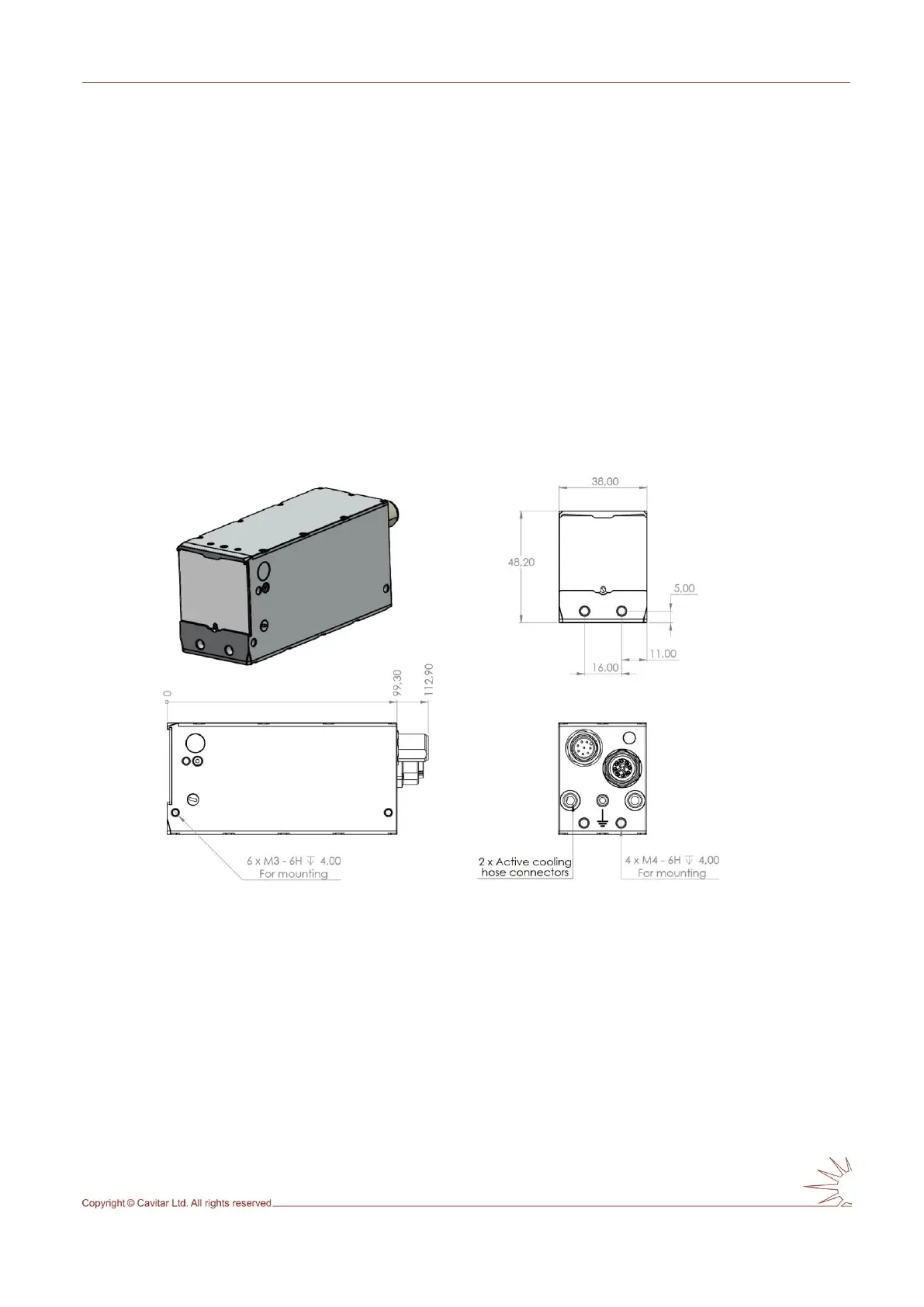
Fig. 3.4. Camera unit mechanical drawing.