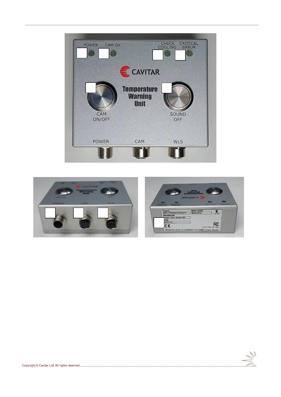
Fig. 3.5. Temperature warning unit (top view).
Fig. 3.6. Temperature warning unit (front view). Fig. 3.7. Temperature warning unit (back view).
In Figs. 3.5-3.7:
A POWER led (green)
B CAM OK led (green)
C CHECK COOLING led (orange)
D CRITICAL ERROR led (red)
E CAM ON/OFF button
F SOUND OFF button
G Connector for power supply (M12, A-coded, 8-pin, male)
H Connector for power cable (M12, A-coded, 8-pin, female)
I Connector for optional warning light system (WLS) (M12, A-coded, 5-pin, female)
J Temperature warning unit device label