Memory Dialing
Operator Extension Setting
Password
PBX Version
Redial
Resetting the PBX programming
Ring Time Settings
Troubleshooting
Technical Specifications
Warranty claim details
NOTE- CCL Epabx reserves the right to alter equipment specifications and description contained herein and makes no
commitment to update or keep current the information herein. All information herein is subject to change at any
time without notice. No part of this publication shall be deemed to be part of any contract or commitment
whatsoever.
-
Product specifications and features are subject to changes without prior notice due to our constant endeavor to improve
the product.
-
All features mentioned in this manual are not part of standard systems. Some features need optional
hardware/software up-gradation.
-
Not every feature in this manual is likely to have been installed in your system or extension.
All Junction lines of the PBX are Disabled in default. To enable them refer heading “Junction Line - Enable /
Disable “
Cabling
-
All cables of the EPABX should be at least 6” away from the electrical cables.
-
They should be at least 12” away from the area of high frequencies like tube light
chokes, Electric Motors, etc. If it is not possible to avoid, then use shielded cables
and earth the shield.
Location
-
The PBX should be installed in a well-ventilated area and at a place where there is no chance of liquid spilling over it or
moisture getting into it (Like in the Bathrooms etc).
-
Direct sun light should not fall on the PBX.
-
The PBX should be installed on the wall at a minimum of 2 ft height from the floor.
Note: The Company’s warrantee voids if the above points are not followed.
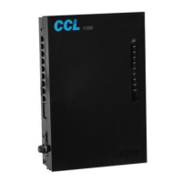
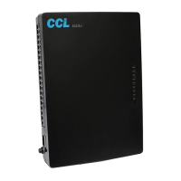
Front Panel Indications
Following is the descriptions of the LED indicators of the front panel of the PBX:
LED Name Description
POWER Blinking means PBX is working on Mains AC or Battery.
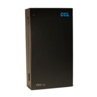
Connections
The PBX has the following connectors on its side panel:
Connectors Description
LINE 1 Terminate the 1st Junction Line here through a RJ Connector.
EXT 601 Terminate the 1st Extension wires over here through a RJ Connector.
EXT 602 Terminate the 2nd Extension wires over here through a RJ Connector.
EXT 603 Terminate the 3rd Extension wires over here through a RJ Connector.
EXT 604 Terminate the 4th Extension wires over here through a RJ Connector.
EXT 605 Terminate the 5th Extension wires over here through a RJ Connector.
EXT 606 Terminate the 6th Extension wires over here through a RJ Connector.
EXT 607 Terminate the 7th Extension wires over here through a RJ Connector.
EXT 608 Terminate the 8th Extension wires over here through a RJ Connector.
AC 220V Connect the 2-pin main lead.
Switch at the Bottom of the PBX