14 INSTALLATION MANUAL
INPUTS AND OUTPUTS
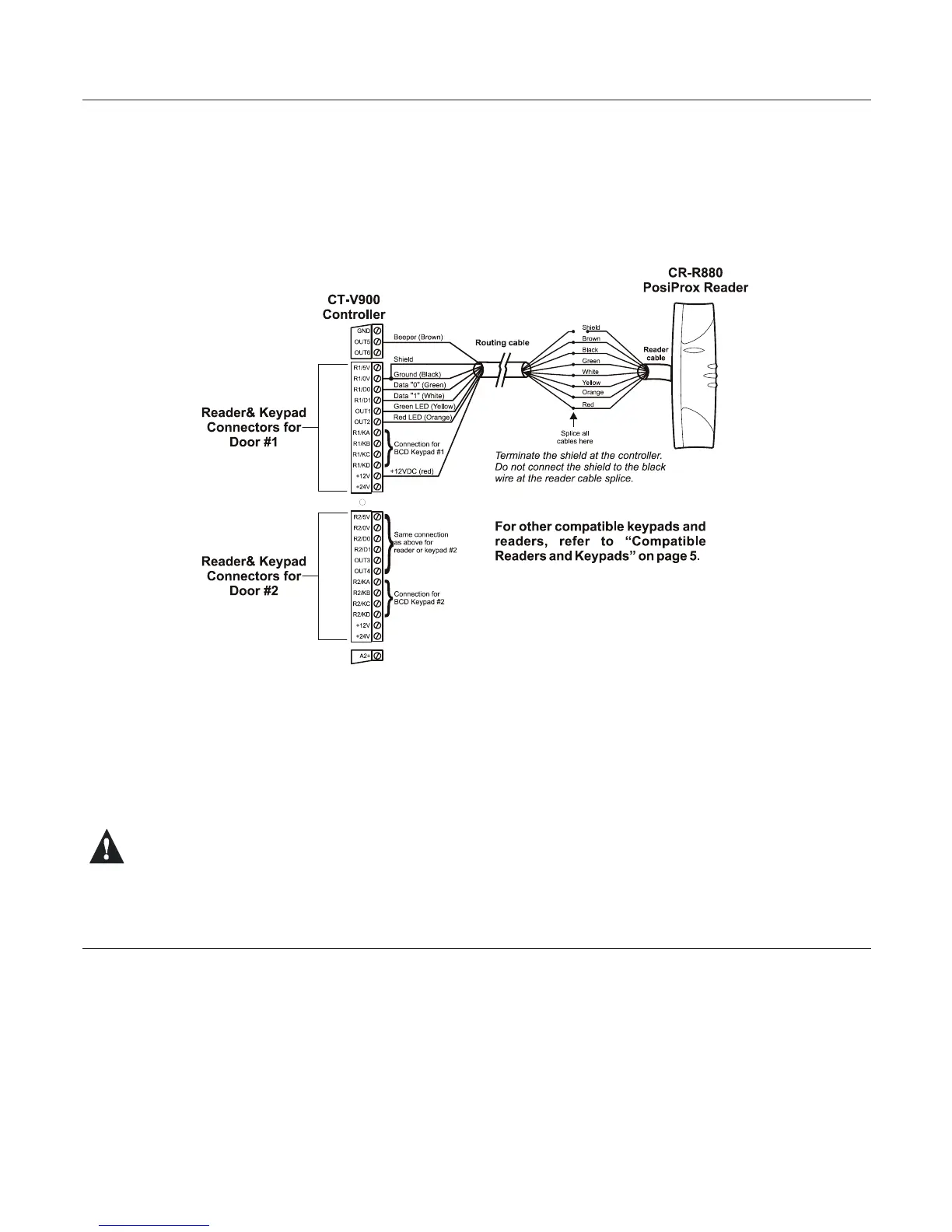
READERS AND KEYPADS
Each CT-V900 controller supports up to two readers and two keypads. With some congurations this can be
expanded to a maximum of four readers and four keypads. If you are using the Anti-Passback mode, you will be
limited to two controlled doors or one entry/exit door. Most Wiegand keypads and readers are connected as shown
below. When installing a keypad with a Wiegand output, the keypad’s “D0” and “D1” wires should be connected to
the same terminals as the reader’s (the reader output must be open collector). Depending on the required
application more than one keypad and/or reader can be connected to the same terminals.
Figure 10: Reader and Keypad Connections
Belowyouwillndexamplesofthemanydoorcongurationsthatarepossible.Fordetailsanddrawingsofsome
of these example refer to “Diagrams” on page 19.
• Controlled entry with free exit (request for exit via detector or button)
• Keypad only entry with free exit
• Controlled entry and exit by using 2 readers per door (no entry or exit registration)
• Controlled entry and exit by using 2 readers and 2 keypads per door (no entry or exit registration)
• Reader entry with keypad exit (single or multiple codes)
• Controlled entry and exit with Anti-Passback and registration of entry and exit (uses 2 reader ports and 2 doors)
Using the wrong voltage may damage your reader or keypad and invalidate the controller warranty.
PROGRAMMABLE OUTPUTS
Most readers and keypads have built-in buzzers and LEDs. These should be connected to controller’s
programmable outputs (OUT1 to OUT6) as shown in Figure 10. These are open collector outputs capable of sinking
25mAwitha10Ωlimitingresistor.Forinformationonhowtoprogramtheoutputs,pleaserefertotheCentaur
Operator’s Manual. The default settings are as follows:
• Output 1 - Access Granted Door 1
• Output 2 - Access Granted Door 1
• Output 3 - Access Granted Door 2
• Output 4 - Access Granted Door 2
• Output 5 - Waiting for Keypad Door 1
• Output 6 - Waiting for Keypad Door 2
Typically, a red/green indicator on the reader will inform the card user that access has been granted (changes from
www.cdvgroup.com