LOCATION & INSTALLATION
CONTENTS OF CT-V900 PACKAGE
WhenyoureceiveyourCT-V900controlleryoushouldndthefollowingitemsinyourpackage.Ifyouaremissing
any items, notify your distributor immediately.
• 1 CT-V900 Controller in its cabinet • Backup battery lead wires
•EOLresistorsforcontrollerinputs(8X2.2KΩand16X1KΩ) •CT-V900cabinetkeys
• 2 (8) diodes for the door strikes or locks • Tamper switch and metal bracket
LOCATION AND MOUNTING
The cabinet is designed to be installed indoors, in a safe and secure location. Suggested locations include electrical
rooms, communication equipment rooms, closets or in the ceiling. To save time and wiring and facilitate testing,
install the cabinets at an equal distance between its controlled doors. Normal temperature and humidity levels
should be maintained.
• Cabinet Dimensions:
39cm (15.5”) high, 33cm (13”) wide, 10cm (4”) deep
• The Cabinet Can Accommodate:
Two 12V, 7Ah, gel cell type batteries and wiring connections
15cm (6”) high, 6cm (2.5”) wide, 10cm (4”) deep
• Multiple Conduit Knock-outs:
Two 25mm (1”) or 31mm (1.25”) and one 12mm (0.5”) or 19mm (0.75”) on each side
• Minimum Clearance For Cabinet:
25cm (10”) clear space around all sides
38cm (15”) clear space in front of cabinet
• Minimum Clearance From Electrical Interference:
2.4m (8ft.) from high voltage equipment or wiring and from electrical equipment likely to generate interference
1.2m (4ft.) from telephone equipment or lines and 8m (25ft.) from transmitting equipment
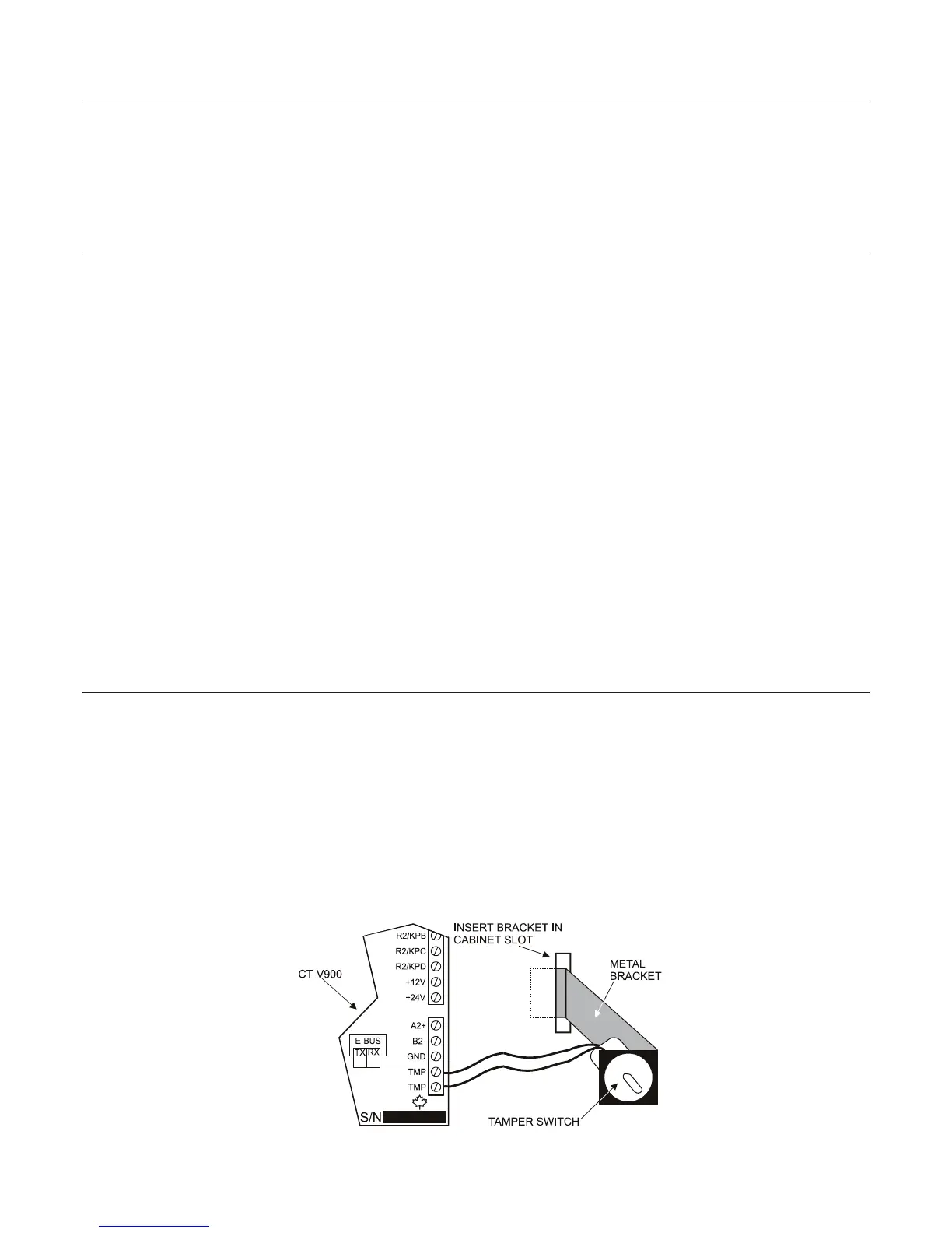
INSTALLING A CONTROLLER BOX TAMPER SWITCH
Installing a tamper switch allows the controller to detect when the cabinet door is opened or when the cabinet is
removed from the wall. Refer to Figure 1 and install the tamper switch as follows:
STEP 1: Insert the metal bracket in the cabinet slot before installing the cabinet on the wall.
STEP 2: Insert the tamper switch in the metal bracket’s 2cm (0.75”) hole.
STEP 3: Connect two 20cm (8”) wires to the tamper switch terminals.
STEP 4: Connect the tamper switch to the “TMP” terminals on the controller.
STEP 5: If you do not use the tamper switch, connect a wire between the two “TMP” terminals.
Figure 1: Tamper Switch Connections
6 INSTALLATION MANUAL www.cdvgroup.com