CT-V900 CONTROLLER 15
redtogreen),accesshasbeendenied(ashingred),orthedoorislocked(solidred).Typically,thereaderbuzzer
or an external sounding device will inform the card user that the door has been left open after a valid access or the
door has been forced open. The functions of all these outputs are programmable through the Centaur software.
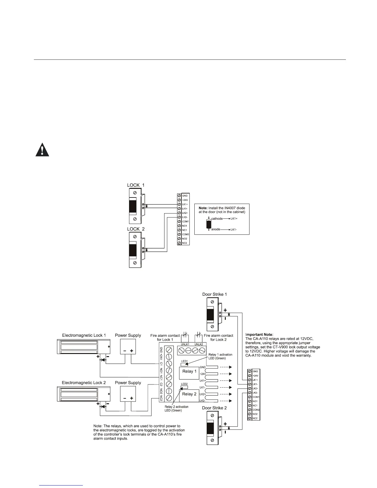
Figure 11: Connecting Locking Devices
LOCKING DEVICES
Each controller has two lock outputs and each of these outputs is associated to a reader input. Using the lock output
jumpers you can set each lock output to provide 12VDC or 24VDC (see “Jumper Settings” on page 8). A lock output
voltage of 24VDC is recommended for most locking devices. Lock outputs are protected by fuseless technology and
will shutdown if the current exceeds 800mA @ 12/24VDC.
• If you have one door with a reader on each side of the door, you can use either lock output.
• You can program the lock outputs to function in “fail-safe” (remove power to unlock a door) or “fail-secure” mode
(power required to unlock a door).
•WhenusingElectronicMagClampsorsimilardevicesensurethatthecurrentspecicationsarenotexceeded.
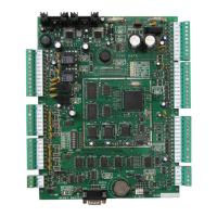
• When interconnection to a re alarm systemis required, we recommend theCA-A110 Lock ControlModule.
Thismodulecanbeusedtocutpowertothelocksduringarealarm.Refertothemodule’sinstallationinstructions
for connection of the CA-A110 device.
Always consult the regulatory agency in your area for existing regulations regarding doors designated as
emergency exits.
Figure 12: Connecting Locking Devices using CA-A110 Lock Control Module
www.cdvgroup.com