CONNECTING EARTH GROUND
Acoldwaterpipeprovidesthebestearthgroundforthesystem.Ifacoldwaterpipeisnotavailable,ndanothergood
earth ground. Run an AWG #14 solid copper wire from the controller’s EARTH GND terminal (located on top right of
controller) to the cold water pipe. Place the ground clamp below any other ground clamps on the same water pipe.
POWER CONNECTIONS
A 15 amp AC power source with a dedicated breaker and an isolated ground is recommended. Connect a 24VAC,
75VA (minimum) transformer to the controller’s AC terminals and mount it near the cabinet. Wire two 12VDC, 7Ah,
gel type batteries in series and then connect them to the BAT+, BAT- terminals with the battery leads supplied (see
“Figure 14” on page 19).
Do not power up the controller until all connections are completed.
BATTERY BACKUP
The controller cannot be started on battery power only. Battery backup time varies with each system. Typical backup time
is between 2 and 20 hours using standard equipment and settings. When the battery voltage drops below 20.5V the LOW
BATLEDwillash.Itwillrestoreat23.4V.Ifthebatteryvoltagedropstobelow16.8V,thecontrollerwillshutdownafter
oneminute.TheLOWBATLEDwillashtwiceasfast(strobe)duringthisoneminuteperiod.
LED INDICATORS
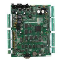
For location of LEDs refer to “Figure 2” on page 8.
UPON POWER UP
• The “AC PRESENT” LED should be on.
• The “READER 5 VOLT” LED should be on.
• The “12 VOLT SUPPLY” LED should be on.
• The “LOGIC 5 VOLT” LED should be on.
•The“MICROCHECK”LEDashesevery750msinnormaloperationorevery350ms
if communication fails.
• When a valid card is presented at either reader, the LED indicator associated with the reader activates
for 750ms.
• When a card is presented to a reader that does not conform to the programmed format, the LED
indicator associated with the reader will activate for 100ms.
If the “micro check”, “low bat”, “reader 1” and “reader 2” LEDs are ashing in a circular manner,
the controller has no rmware and must be updated. The update can be done from the rmware update
application which can be downloaded from our web site. For more information refer to the Centaur
Operator’s Manual or visit our web site at www.postech.ca.
BATTERY INDICATIONS
• During a battery test, the “BATT CHECK” LED should be on for four seconds.
• When there is a complete loss of power (no AC or battery), the “BATT ENABLE” LED should be off.
•Whenthebatteryvoltagedropsbelow20.5Vthe“LOWBATT”LEDwillash
• If the battery voltage drops to below 16.8V, the controller will shut down after one minute.
The“LOWBATT”LEDwillashtwiceasfast(strobe)duringthisoneminuteperiod.
CT-V900 CONTROLLER
7www.cdvgroup.com