8
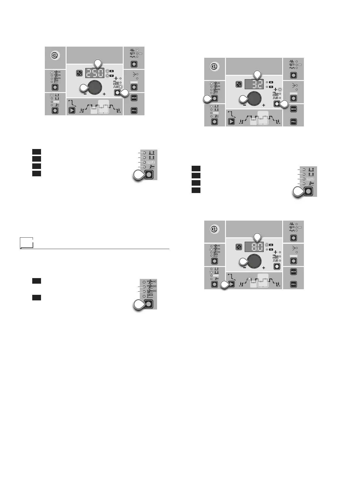
To regulate the FREQUENCY push the BALANCING and
FREQUENCY key (T4) (FREQUENCY LED flashing) and
use the ENCODER Knob (E) to regulate the value indicated
on the DISPLAY (D).
CYCLE
HOT
START
ARC
FORCE
I2
PULSE
CYCLE
f
I
1
Ip
Ib
Ø
WAVE
ON
FAST
ULTRA
FAST
SLOW
SYN
PULSE
E
T4
D
To exit, simply push the BALANCING and FREQUENCY (T4)
key again (FREQUENCY LED off).
7) Press the WELDING MODE SELECTION Key (T9) and go to
one of the 4 options available:
L5 2T
L6 4T
L7 CYCLE
L8 SPOT WELD
T9
L6
L7
L8
8) By pushing the WELDING PARAMETERS SELECTION key
a number of times it is possible to set the various TIG WELD-
ING PARAMETERS (see the “TIG AC and DC Welding” par-
agraph - WELDING PARAMETERS).
9) Once the all the selections/regulations indicated above have
been made, welding can begin.
10) During the welding process the DISPLAY shows the real Amps
(A) at which the operator is actually welding.
TIG “DC” welding
1) Start the welding machine by turning the power supply switch
to position I.
2) Press the WELDING PROCESS SELECTION Key (T7) and
select:
L2 a TIG “HF DC” welding process
for direct current TIG welding with
high frequency ignition.
L3 a TIG “Lift DC” welding process
for direct current TIG “Lift” type weld-
ing without high frequency.
T7
L2
L3
WARNING: The “Lift” ignition current is created by pushing
the torch button only after having touched the workpiece with
the electrode.
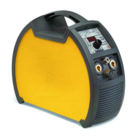
3) ELECTRODE DIAMETER SELECTION
Select the diameter of the electrode to achieve the best control
of ignition in a synergic manner. Selection is done by pushing
the ELECTRODE DIAMETER Key (T4) (ELECTRODE DIAM-
ETER LED flashing) and using the ENCODER Knob (E) to
regulate the value indicated on the DISPLAY (D).
WAVE
ON
FAST
ULTRA
FAST
SLOW
SYN
PULSE
CYCLE
HOT
START
ARC
FORCE
I2
PULSE
CYCLE
f
I
1
Ip
Ib
Ø
T7
E
T4
D
To confirm the diameter selected, simply push the ELEC-
TRODE DIAMETER Key (T4) again (ELECTRODE DIAME-
TER LED off).
4) Press the WELDING MODE SELECTION Key (T9) and go to
one of the 4 options available:
L5 2T
L6 4T
L7 CYCLE
L8 SPOT WELD
T9
L5
L6
L7
L8
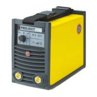
5) Turn the ENCODER Knob (E) until the DISPLAY (D) shows
the CURRENT VALUE at which you wish to weld.
CYCLE
HOT
START
ARC
FORCE
I2
PULSE
CYCLE
f
I
1
Ip
Ib
Ø
WAVE
ON
FAST
ULTRA
FAST
SLOW
SYN
PULSE
E
D
T10
6) By pushing the WELDING PARAMETERS SELECTION (T10)
key a number of times it is possible to set the various TIG
WELDING PARAMETERS (see the “TIG AC and DC Weld-
ing” paragraph - WELDING PARAMETERS).
7) Once the all the selections/regulations indicated above have
been made, welding can begin.
8) During the welding process the DISPLAY shows the real Amps
(A) at which the operator is actually welding.