5
2 - SPECIAL CONFIGURATION
(only for expert welders)
TIG welding
For this configuration, in addition to the parameters already de-
fined for the STANDARD configuration, you can also set the fol-
lowing parameters:
L9 IGNITION CURRENT
WARNING: This can only be programmed when the TIG AC with
HF ignition or TIG DC with HF ignition welding processes are
used.
L9 IGNITION TIME duration
WARNING: Only programmable when the TIG AC with HF igni-
tion welding process is activated.
L16 INITIAL welding CURRENT
WARNING: This can only be programmed when the TIG AC with
HF ignition or TIG DC with HF ignition welding processes and
the 2 STROKES welding mode are used.
L20 FINAL welding CURRENT
WARNING: This can only be programmed when the TIG AC with
HF ignition or TIG DC with HF ignition welding processes and
the 2 STROKES welding mode are used.
HOT
START
ARC
FORCE
I2
PULSE
CYCLE
f
I
1
Ip
Ib
WARNING: This special parameter is only to be activated by
qualified personnel, or those trained by technicians.
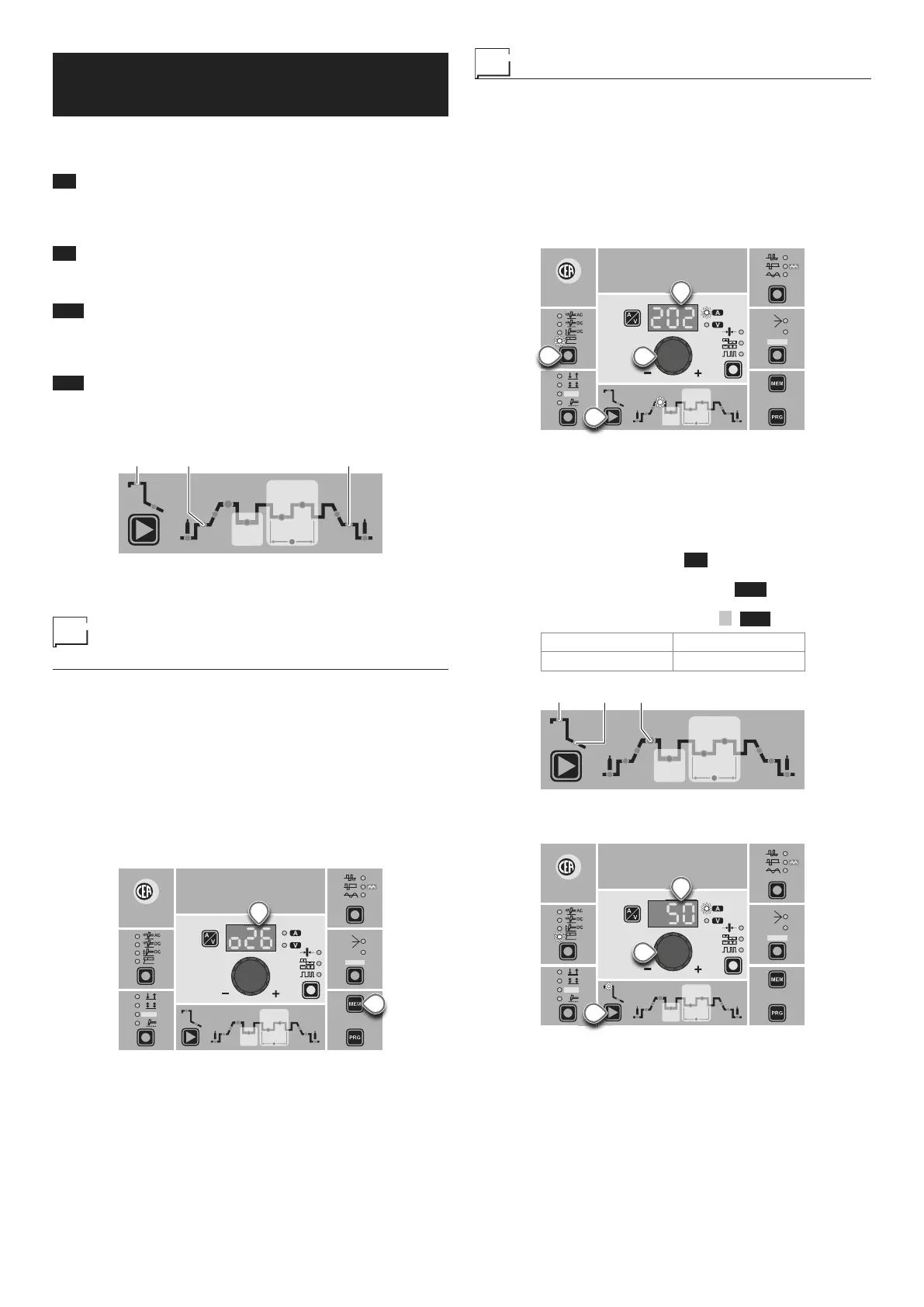
Displaying the software
version installed
The MATRIX AC/DC are fitted with a digital control with software
on board defined in the factory. This software is subject to contin-
uous evolution and improvement. The software is identified by a
specific number that can be viewed on the DISPLAY (D) as follows:
1) When the welding machine is off, push and hold the “MEM”
SAVE key down (T1).
2) Start the welding machine by turning the power supply switch
to position I.
3) For a few seconds the DISPLAY (D) shows the type of soft-
ware on board (e.g. o26) where:
• o indicates the welding machine model.
• 26 indicates the VERSION of the software installed
WAVE
ON
FAST
ULTRA
FAST
SLOW
SYN
PULSE
CYCLE
HOT
START
ARC
FORCE
I2
PULSE
CYCLE
f
I
1
Ip
Ib
Ø
T1
D
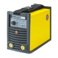
Electrode welding (MMA)
1) Start the welding machine by turning the power supply switch
to position I.
2) WELDING PROCESS SELECTION
Push the WELDING PROCESS SELECTION key (T7) to se-
lect the ELECTRODE welding processes for welding with
“HOT START” or “ARC FORCE” devices that can be pro-
grammed by the user.
3) Turn the ENCODER Knob (E) until the DISPLAY shows the
CURRENT VALUE at which you wish to weld, in relation to
the diameter of the electrode you are using.
WAVE
ON
FAST
ULTRA
FAST
SLOW
SYN
PULSE
CYCLE
HOT
START
ARC
FORCE
I2
PULSE
CYCLE
f
I
1
Ip
Ib
Ø
T7
E
T10
D
4) WELDING PARAMETERS SELECTION
To refine the weld quality, the following parameters can be set
by pushing the WELDING PARAMETERS SELECTION key
(T10) in succession:
•
HOT START - This increases the welding current, in per-
centage terms, for a time interval that can be set at the start
of the welding process, thereby reducing the risk of poor fu-
sion at the start of the joint ( L9 - HOT START - 00-100).
•
MMA ARC FORCE - Regulates, in percentage terms, the
dynamic characteristics of the arc ( L10 - ARC FORCE -
00-100).
• PRINCIPAL welding CURRENT I
1 ( L11 ):
4000 AC/DC 5000 AC/DC
10 ÷ 400 A 10 ÷ 500 A
HOT
START
ARC
FORCE
I2
PULSE
CYCLE
f
I
1
Ip
Ib
The value for the welding parameters can be regulated using
the ENCODER Knob (E).
CYCLE
HOT
START
ARC
FORCE
I2
PULSE
CYCLE
f
I
1
Ip
Ib
Ø
WAVE
ON
FAST
ULTRA
FAST
SLOW
SYN
PULSE
T10
E
D
5) To exit these functions hold the WELDING PARAMETERS
SELECTION key (T10) down for about 1 second.
6) Once the all the selections/regulations indicated above have
been made, welding can begin.
7) During the welding process the DISPLAY (D) shows the real
Amps (A) at which the operator is actually welding.